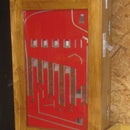
Introduction: DIY Keyboard Controller for MAME and Virtual Pinball
This set of instructions allows you to fabricate your own keyboard controller using old keyboards for the cost of some wire, solder and a piece of wood.
These controllers have been used in my MAME and Virtual Pinball projects.
See Virtual Pinball Instructable https://www.instructables.com/id/Virtual-Pinball-M...
See Camel Racing Instructable https://www.instructables.com/id/Camel-Racing-Arab...
I have used old USB and PS2 keyboards that were intended for disposal. Keyboards that were dirty or had broken keys were good for my project as all I need is the small circuit board inside.
The following set of instructions demonstrates how to make a controller from an HP PS2 keyboard.
Supplies
Old Keyboard
0.5mm wire
Solder
Silicone Sealant
Connector Block
Step 1: Strip Circuit From Old Keyboard
Remove any screws on back of keyboard to open it up and expose the circuit board. Remove any screws mounting the circuit board to the casing and retain these circuit mountings as these will be used to mount the circuit on the new controller.
Step 2: Mount Circuit Board to Wood
Mount circuit board to suitable size piece of wood. Wood needs to be large enough for cable connector block as well as the printed circuit. Note the keyboard LED’s are visible underneath where notch in wood has been cut out.
Step 3: Connecting Wires to Circuit Board
Prepare 200mm lengths of 0.5mm cable, Trim back ends by 5mm and solder one end of each cable.
Solder will not bind to the conductive material of the keyboard connectors. Carefully use emery paper to remove this film and expose the gold\copper underneath. On the first picture above the longest edge has been prepared.
Solder each of the keyboard connectors, then solder the 200mm lengths of cable to the circuit board.
Restrain cables, using mountings from keyboard, by screwing straps across them to avoid any accidental damage to the circuit board if a cable were pulled.
Test each of the cables are connected properly by using a tone meter connected to one end of a cable and to the circuit board soldering point at the other. Once tested successfully, cables should be glued or siliconed into place to avoid any accidental pulling on soldered joints. Leave for silicone to cure before using new controller
Step 4: Mapping Keys
Number each connector on the wood. On the longer edge I have written 1 to 18 on the wood and A to H on the shorter connector.
The above table is the keyboard map for the HP keyboard in this example. When connecting to my Virtual Pinball, the left flipper on Visual Pinball software is set to LEFT SHIFT button. So I wire left button on my machine to pins 3 and 14 on this controller.
To map a new keyboard, you need a keyboard tester application on your computer or use a trusted online keyboard tester.
Write down all permutations that need to be tested, eg A&1, B&1, C&1, D&1 ... 17+18.
Short out each pair and note which key press the tester detects.
Note, save all your work before carrying out such keyboard mapping as there is a pair that shuts down your machine and a pair that restarts your machine. I use the shutdown button on my machines so I can shut machine down cleanly before powering off without needing to open game up.


