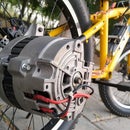
Introduction: DIY Miniature Gasoline Generator
In this insctrutale, I am going to built a miniature DC generator that is powered by a four stroke gasoline engine. It can be a great tool for off grid power or charging your car battery when you are miles away from a power socket as the whole unit is quiet compact and wieghts arround 8 kg.
The idea is to built a small gasoline powered generator thats able to charge batteries or can power appliances using an inverter. To make it possible what we have got is a small four stroke 36cc Gasoile Engine. These are compact engines that are usually built to power tools such as a leaf blower or a string trimmer. Luckily we have got one in brand new condition and thats how we got through this project.
Ready set built....
Step 1: Tools and Materials
The steps to this project might involve a bunch of tools but you can do the same with a bunch of other tools, inshort the goal is to get the job done so no comphrensive list of tools.
For the material and stuff , you are going to need the following:
- A small Gasoline Powered Engine
- An old hoverboard motor
- chain spockets
- Chain
- Metal tubes and sheet
- Nut and bolts
- Aluminium spacers
- A rectifier unit
- Rubber pads
- Fuel bottle. etc
Step 2: Selecting the Generator
To convert the mechanical energy into electrical energy we are going to need a permanent magnet motor. Now brushed motors are a simple way to go but they are most likely to get their brushes weared out soon and doest seems to offer a good efficiency. So, we have to go with a brushless motor to eliminate this problem.
One such motor is used in hoverboards, yes each wheel of a hoverboard is a permanent magnet brushless motor. With the outer casing containing the magnets that spins across the coils, so as you give the motor a quick spin it proudces electricity.
Now the good thing about this motor is that its highly efficient and it can produce a good range of voltage on a relatively slow RPM. To be accurate it produces 40 volts as you spin the motor at nearly 700 RPM. But the down side is that the electrical energy it produces is a three phase altyernating current which we have to convert into direct current.
Now the first thing we did is to extract the motor out of the hoverboard which is just a matter of removing the casing and unscrew the motor coupling.
Once we get our hands on the motor, we dismentalled the motor and removed the tyre which is no more needed. To drive the motor what we are going to do is to attach a spocket to the motor casing using a couple of 6mm nutbolts tighten across the motor casing.
Once we get that done, the motor is assembled and is ready to be used.
Step 3: Centrifugal Clutch
These engines comes with a centrifugal clutch assembly which allows the engine to engage to the external load when the throttle is pulled. Since I am planing to use this engine to experriment with fuel other than gasoline. So to make the tuning process easier I have attached a centrifugal clutch assembly. You can skip this step if you are planing to run it on gasoline only.
To drive the motor I have used a smaller chain spocket having 7 teeths.
Step 4: Framing
For holding everything together we are going to use 1 inch square metal tubing. A pair of tubes run across the length of the unit and holds everything with the help of 4mm thick metal sheet and a bunch of spacers as shown.
Step 5: Assmebling the Frame
The metal tubes are first attached to the enigne using a couple of allen bolts. Next the spacers are added with the metal plate in its place. Now with everything tightned up its time to mount the motor.
Step 6: Mounting the Motor
The motor is mounted to the metal plate using its original coupling that comes with the hoverboard. The chain is placed across both the spockets and the coupling is then tightened up.
Step 7: Base Mount
As we finished mounting the motor I have realized that the weight of the whole unit is shifted towards the front of the unit causing it to fall over.
To get the CG within the base frame I have added two metal strips on either ends with four rubber feets mounted across each corner. The gives the whole frame a nice stablity and stops the unit to move here and there due to viberation.
Next we have added a fuel bottle to the bottom of the frame using a bunch of cable ties. The fuel tubes are then connected to the carbeurator.
Step 8: Rectifier Unit
As we have discussed earlier, our generator is going to produce a three phase alternating current. Now to make it useful we have to rectify it to convert it into more useful direct current.
Upto thsi point the unit seems like a great built so to keep up the great work what I have decided to do is to built the rectifier unit using customized PCBs. Now that might sounds complicated and and expensive job but with JLCPCB you can get you hands on customized PCBs at a great price and the quality is just unmatchable.
So To order The PCBs I have uploaded the gerber files and after going through a bunch of options, the order is complete. And thats how simple is that, so have a look at their website for some great quality PCBs at an outstanding price.
Project files:
https://easyeda.com/diyking/diy-three-phase-rectif...
https://easyeda.com/editor#id=|31478ddb75014415afa...
Gerber Files Bill of Material and schematic:
Step 9: Assembling the Rectifier Unit
We have recieved the PCBs within just a week and the quality is flawless. Next we gathered all the components and witht that its just a matter of dropping all the compionents in place and sotter them.
With the rectifier unit ready its time to mount it on our generator and test it out.
Step 10: Final Results
With a couple of pulls on the kick starter the engine started and seems to run perfectly. As the speed of the engine is increased the centrifugal clutch engaged and started to spin the motor.
At nearly 40% throttle the generator produces nearly 36v and a total output of 250 watts which is quiet sufficient for unit this compact. Now this generator can be couplet with a buck/boost converter to power DC loads or to charge a battery. To power AC appliances, we need to connect the DC output to an inverter.
The generator wieghts around 8kg and can be a useful tool for charging your battery or powering you AC appliances when you are miles away from a power socket.
That was a fun project, will see you guys with the next one.
Regards.
DIY King


