Introduction: DIY 2000 Watts PWM Speed Controller


I have been working on converting my bicycle to an electric one using a DC motor for automatic door mechanism and for that I have also made a battery pack thats rated at 84v DC.
Now we need a speed controller that can limit the amounbt of energy delivered to the motor from the battery pack. Most of the speed controller avliable online are not rated for that much high voltage so I decided to built one for myself. So thats whats this project is going to be, to design and built a customized PWM speed controller to controll the speed of large scale DC motors.
Step 1: Tools Materials and Skills


For this project you need basic soldering tools such as:
- A soldering iron
- Sucker
- Pliers and twizzers
The schematic, Gerber files and the list of comonents is avliable here.
Step 2: Designing the Speed Controller


Since we are aiming to con trol the speed of a DC motor for which we can use two techinquies, A buck converter which will stepdown the input voltage buts its a rather complicated one so what we have decided to go with is PWM Control (Pulse Width Modulation). The approach is simple, to control the speed the battery power is switched on and off at a high frequency. To change the speed the duty cycle or the on off time period of the switch is changed.
Now mechanical switches are not expected to undergo such high stress so an appropriate choice for such application is an N-Channel Mosfet that are specifically made to handle moderate amount of current at high frequency.
To switch the mosfets we need a PWM signal which is produced by a 555 timer IC and the duty cycle of the switching signal is varied using a 100k potentiometer.
Since we cant operate 555 timer above 15v so we incorporated a lm5008 Buck converter IC which steps down the input voltage from 84VDC to 10VDC which is used to power the timer IC and the cooling fan.
Now to handle the large amount of current, I have used four N-Channel Mosfets that are connected in parallel.
Besided that I have added all the complimentary components as described in the datasheets.
Step 3: Designing the Printed Circuit Boards


As I finished the schematic I have decided to go with designing a dedicated PCB for the speed controller as it will not only help us to keep everything neat but I intended to design this unit so thats its capable of further modifications for my other DIY projects that uses large DC motors.
The idea of designing a PCB might seems to take a whole lot of efforts but believe me it worth that all when you get your hands on customized boards. So with that in mind I designed the PCB for the speed controller unit. Always try to define particular regions such as the control circuitry and the power on the other side so that when you are connecting everything together you are good to go with appropriate track width specially on the power side.
I have also added four mounting holes which will be helpful to mount the controller and also hold the colling fan along with the heat sink above the MOSFETs.
Step 4: Ordering the PCBs


Unlike any other customized part for your DIY Project, PCBs are surely the easiest one to get. Yes Now once we generated gerber files of our finilized PCB layout we are jjust a few clicks away from ordering our customized PCBs.
What all I did is to head upto PCBWAY and after going through a bunch of options there I uploaded my gerber files. Once the deisgn is checked for any errors by their techinical team your design is forwarded to the manufacturing line. The whole process will take two days to completa and hopefully you will get your PCBs within ust a week.
PCBWAY have made this project possible by their support so take your time and have a look at their website. They are offering Standard PCB, Quick-turn PCB, SMD etc so for discounts of upto 30% on your PCBs visit this link.
Gerber files,schematic and the BOM(Bill Of Material) for the speed controller PCB is avliable here.
Step 5: Assembling the PCBs


As expected the PCBs arrived within a week and the finish is just too good. The quality of the PCBs is absolutely flawless. Now time to gather all the components as mentioned in the BOM(Bill of Material) and drop them in place.
To keep things flowing we need to start with the smallest component on the PCB which in our case is LM5008 Buck converter, an SMP component. Once we sottered it using soldering braid as we dont have a hot gun to deal with SMD component, we than sottered the inductor next to it and moved towards larger components.
Once we are done assembling the boards, Its time to drop the 555 timer in place with the notch in correct direction.
Step 6: Cooling Things Up


With this much amount of power that we are going to deal with, obviously things are expected to heat up. So to deal with that we are going to bend the MOSFETs and mounted a 12v fan with the heat sink sandwitched inbetween.
With that being done, the beast of a PWM speed controller is ready to roll.
Step 7: Testing the Controller


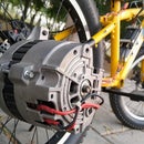
To test the controller we are goint to use an 84v customized battery pack that we have built for our electric bicycle. The controller is temporarily connected to the battery pack and the motor that is attached to the bicycle to drive the rear wheel.
As I toggled the switch, the controller is powered on with the fan blowing air over the MOSFETs. As I turned the potentiometer clockwise, the motor started to rotated and gradually increasing the speed proportional to the rotation of knob.
Step 8: Final Results


At this stage the speed controller is ready and it went way beyound my expectations as far as the finish is concerned. The controller seems to operate easily on 84v battery pack and controlls the speed of the motor smoothly.
But to test this speed controller on load we need to finish our bicycle project and mount everything in place. So guys for on load performance stay tuned for the upcoming project video which is a DIY electric bicycle conversion project.
Subscribe and stay tuned for upcoming project video.
Regards.
DIY King


