

Introduction: DIY Smart Home With Google Assistant and Arduino


Who doesn't want a smart home ? One of the nicest things you can do is switching the lights or other appliances in your house by voice control. With the help of the Google Home app and the Google assistant this is really a piece of cake ……
You do not need many parts for it and it is a nice experiment to build this voice control yourself with a smart speaker, an Arduino mini computer and a few switching relays. You can also buy plenty very cheap smart lights and connction sockets but making it yourself is much more fun. I will describe step by step how you can do this. You will need the following components:
Supplies
1 A smart speaker, for example a Google Nest Mini.
2 An Arduino MKR1000 computer to convert the voice commands into switching commands.
3 One or more 5 Volt switching relays, one for each lamp you want to control.
4 A USB power supply for the Arduino MKR1000 with micro-USB plug.
5 Main wiring (1.5 sqmm) and sockets for a safe connection of the lights and other appliances.
6 An Android smartphone for the Google Home app.
Step 1: The Command Process Via Internet
In this image you can see step by step how the whole process works.
Switching on and off via the voice commands runs completely via the internet. Three (!) cloud services are required to do this... You have to create an account for every cloud service… It is a bit cumbersome but it works!
First you will need the Google Home app. Download it from the Playstore on your Android phone and install the app. Understanding your own voice commands with Google Home only works with the English language. So set the language to English via settings / more settings / assistant / languages and then choose English (United States).
The Google Nest Mini hears the voice command, for example “Hey Google, switch light number one on”. This analog audio signal is digitized and is sent to the Google Assistant cloud. It is then forwarded to the IFTTT cloud where the answer is made. IFTTT (If This Than That or “if you do one thing the other thing happens”) is a kind of intermediate station that analyzes the command, gives the answer and forwards the actions to the next cloud, the Adafruit IO. If the command is fully understood the answer from IFTTT will be returned digitally to the Google Nest Mini and there it will be converted into an audio signal. If the command is not understood, the Google Assistant will return another answer to make it clear that no switching action will follow. A well-understood command will be forwarded by IFTTT to the Adafruit website. Adafruit is an electronics supplier maintaining a website to store smart switching data. They call it a “Feed”. IFTTT sends the code associated with the command (in our case “one_on”) to this feed. The Arduino MKR1000 is programmed to check this website reguarly, reading out the data in the feed and then it switches the relevant switching relay on or off. The Adafruit feed is protected for security reasons with an account name and a unique Adafruit IOKEY only known to the account owner.
Step 2: Programming the Arduino MKR1000

Use the standard IDE from the Arduino website.
Place the following libraries in the IDE (via: tools / manage libraries): ArduinoJson and WiFi101.
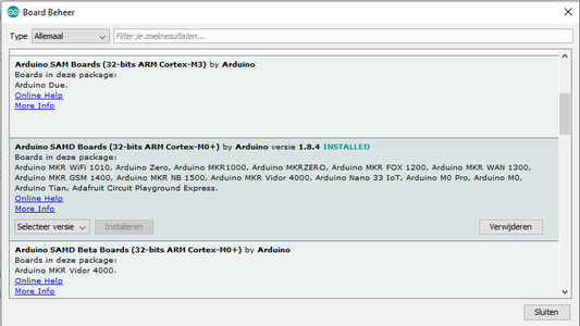
If you have not previously programmed the MKR1000, you must first make this board accessable in the IDE. Download the board file “Arduino SAMD boards” via the menu tools / board / board manager, after which you can select the MKR1000 board.
The sketch also uses an extra file, arduino_secrets.h.
This is a text file that you can create with notepad. This file contains the used access codes for the Wi-Fi network (network SSID and password) and the Adafruit IO web page login codes (account name and IOKEY code). Save this file in the arduino library directory on your PC with the name arduino_secrets.h in a separate directory. Before saving, replace all “xxx” with your own network and Adafruit data. This should be in the arduino_secrets.h file:
#define SECRET_SSID “xxx”
#define SECRET_PASS “xxx”
#define IO_USERNAME “xxx”
#define IO_KEY “xxx”
Copy the Arduino sketch below and load it into the MKR1000 via the Arduino IDE program.
Attachments

Step 3: The Adafruit Feed

Create an account at www.io.adafruit.com. Adafruit is an electronics supplier maintaining a website to store smart switching data.
Create an ON_OFF feed in which the commands will be saved later. Adafruit has an extensive tutorial showing you how to do this:
https://learn.adafruit.com/adafruit-io-basics-feeds/creating-a-feed
It is best to set the “feed” in the feed history to OFF, it is not necessary to remember the switching commands. (the settings are on the right side of the page).
Step 4: The IFTTT Settings


Create an account at www.IFTTT.com. Go to “explore” (top right) and then choose “make your own applets from scratch”. Click on “THIS” and search for google. Choose google assistant. Then choose the first option "say a simple phrase". Then enter the desired command description and the answer to be given.
(In our case “switch all lights on” and “OK. I will switch all lights on. Watch out!”). Then press “create trigger” and in the next screen press “THAT”. Then choose Adafruit and click on “send data to adafruit IO”. The ON-OFF feed appears in the first field and then enter the desired code in the second field (here as an example “all-on”).
Finally, click on “create action” and then on “finish”.
You can also receive a message on your phone to check every time an applet has been active, which is useful for troubleshooting but when everything is working you can turn this off.
If you want to control multiple lights or other domestic appliances, you have to create an IFTTT applet for each command, and the codes stored in the Adafruit feed must correspond to the codes in the Arduino sketch.
Step 5: Test the Connections and the Software

To test the system, you can make a test setup with LEDs instead of relays:
Step 6: Connecting Domestic Appliances


To switch domestic appliances, you must connect switching relays to the ports of the Arduino MKR1000 instead of the test LEDs. Use 1.5 mm2 wiring at the main voltage supply side to connect the appliances and the relay contacts in a safe way.
