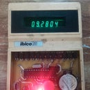
Introduction: DIY Temperature Sensor Using One Diode
So as one of the facts about PN-junctions is that their forward voltage drop changes according to the passing current and to the junction temperature also, we're going to use this to make a simple cheap temperature sensor.
This setup is commonly used in many Integrated Circuits to measure its internal temperature and many temperature sensors as the famous LM35 which is based on this property.
Simply the forward voltage drop of a diode (which is a single PN-junction) changes as the amount of the current passing through it changes, also as the diode temperature changes the voltage drop is going to change (As the temperature increases, the forward drop decreases by a value of (1.0 milliVolts to 2.0 milliVolts for silicon diodes and 2.5 milliVolts for germanium diodes).
So by passing a constant current through the diode the forward voltage drop should now only vary according to the diode temperature.
We just need now to measure the diode's forward voltage, apply some simple equations and voilà here is your temperature sensor !!!
Supplies
1 - 1n4007 diode #1
2 - 1 Kohm resistor #1
3 - Arduino board
Step 1: Circuit Diagram
As you can see in the schematic it's very simple.
by connecting the diode in series with a current limiting resistor and a stable voltage source we can obtain a crude constant current source, so the measured voltage across the diode will only vary due to the temperature change.
Make sure that the resistor value isn't too low that much current passes through the diode and make a noticeable self heating in the diode, also not a very high resistor so the current passing isn't enough to maintain a linear relation between the forward voltage and the temperature.
a 1 kilo Ohm resistor with a 5V supply should result in a 4 milliAmpere diode current which is a sufficient value for this purpose.
I(diode) = VCC / (Rseries + Rdiode)
Step 2: Coding
We need to keep in mind that there are some values to tweak in the code to get the better results like :
1 - VCC_Voltage : as the analogRead() value depends on the VCC of the ATmega chip then we need to add it to the equation after measuring it on the arduino board.
2 - V_OLD_0_C : the forward voltage drop of the used diode at current of 4 mA and temperature of 0 Celsius
3 - Temperature_Coefficient : the temperature gradient of your diode (better to get from the datasheet) or you can measure it using this equation :
Vnew - Vold = K (Tnew - Told)
where :
Vnew = newly measured drop voltage after heating the diode
Vold = measured drop voltage at some room temperature
Tnew = the temperature where the diode was heated to
Told = the old room temperature that Vold was measured at
K = Temperature_Coefficient ( a negative value varying between -1.0 to -2.5 milliVolts )
Finally you can now upload the code and get your temperature results.
<p>#define Sens_Pin A0 //PA0 for STM32F103C8 board</p><p>double V_OLD_0_C = 690.0; //690 mV Forward voltage at 0 Celsius at 4 mA test current
double V_NEW = 0;         //New forward voltage at room temperature at 4 mA test current
double Temperature = 0.0; //Room calculated temperature
double Temperature_Coefficient = -1.6; //-1.6 mV change per degree Celsius (-2.5 for germanium diodes), better to get from the diode datasheet
double VCC_Voltage = 5010.0; //Voltage present at the 5V rail of the arduino in milliVolts (required for better accuracy) (3300.0 for stm32)</p><p>void setup() {
  // put your setup code here, to run once:
pinMode(Sens_Pin, INPUT);
Serial.begin(9600);
}</p><p>void loop() {
  // put your main code here, to run repeatedly:
V_NEW = analogRead(Sens_Pin)*VCC_Voltage/1024.0; // divide by 4.0 if you are using a 12 bit ADC
Temperature = ((V_NEW - V_OLD_0_C)/Temperature_Coefficient);</p><p>Serial.print("Temp = ");
Serial.print(Temperature);
Serial.println(" C");</p><p>delay(500);
}</p>
Attachments
Step 3: Getting Better Values
I think it's advisable to have a trusted temperature measuring device beside you when doing this project.
you can see that there is a noticeable error in the readings that can get to 3 or 4 degrees Celsius so where is this error coming from ?
1 - you may need to tweak the variables mentioned in the previous step
2 - the ADC resolution of the arduino is lower than what we need to detect the small voltage difference
3 - the voltage reference of the arduino ( 5V ) is too high for this small voltage change across the diode
So if you're going to use this setup as a temperature sensor, you should be aware that although it's cheap and handy, it isn't accurate but it can give you a very good idea about the temperature of your system either it's on a PCB or mounted to running motor etc...
This instructable is meant to use the least amount of components possible
But if you want to get the most accurate results from this idea you can do some changes:
1 - add some amplifications and filtering stages using op-amps as in this link
2 - use a lower internal analog reference controller as the STM32F103C8 boards with 3.3 Volts analog reference voltage (see point 4)
3 - use the internal 1.1 V analog reference in the arduino but be aware that you can't connect more than 1.1 Volt to any of the arduino analog pins.
you can add this line in the setup function:
analogReference(INTERNAL);
4 - Use a microcontroller that has higher resolution ADC as STM32F103C8 which has a 12 bit ADC resolution
So in a nutshell, this arduino based setup can give a nice overview about your system's temperature but not so accurate results ( approximately 4.88 mV/Reading )
the STM32F103C8 setup would give you a pretty accurate result as it has a higher 12-bit ADC and a lower 3.3V analog reference value ( approximately 0.8 mV/Reading )
Well, that's it !! :D


