Introduction: DIY Temperature and Humidity Sensor Fire Extinguisher (Arduino UNO)
This project was made to be used by anyone in homes or companies as a temperature and humidity sensor displayed on an LCD and a flame sensor paired with a buzzer and a water pump to extinguish a fire in case of an emergency.
Step 1: Gather the Parts
Parts required:
- Arduino UNO and the IDE(software)
- male to female jumper cables
- male to male jumper cables
- Big breadboard
- Three LEDs (red, yellow and green)
- A 16X2 LCD display with the YWRobot LCM1602 fitted on it
- A flame sensor
- DHT11 Temperature and Humidity Sensor
- A buzzer
- Water pump with battery and two buttons from a self-serve rechargeable water dispenser (used on 5-gallon water bottles)
- Water pump tubing
- 5 Volt relay
- Hand drill
- Sanding brick/paper/machine
- Fretsaw
- Acrylic of your choice
- 330/500ml waterbottle (used as an emergency water reservoir).
- Glue gun
- Acrylic glue
- (OPTIONAL) 9v battery connector
- 3M rubber style double sided tape
Step 2: Make the Connections Between All Parts and the Arduino
Here is a list of the required connections to the Arduino:
LCD
A5 to SCL
A4 TO SDA
VCC TO POSITIVE BREADBOARD
GND TO NEGATIVE/GND BREADBOARD
------------------------------------------------------------------------------------------------------------------------------------------------------
DHT11 TEMP N HUMIDITY SENSOR
A0 (Arduino) TO DIGITAL OUT ON SENSOR
+ TO POSITIVE BREADBOARD RAIL
- TO NEGATIVE BREADBOARD RAIL
------------------------------------------------------------------------------------------------------------------------------------------------------
FLAME SENSOR
VCC TO POSITIVE BREADBOARD RAIL
GND TO NEGATIVE BREADBOARD RAIL
D0 TO PIN 3 ARDUINO
A0 (SENSOR) TO A1 (ARDUINO)
WATERPUMP AND RELAY
GND ON RELAY TO NEGATIVE ON BREADBOARD
5V TO POSITIVE PIN BREADBOARD
SIG TO PIN 13 (ARDUINO)
IMPORTANT!!! REMOVE THE SECOND BUTTON FROM THE WATER PUMP AND ATTACH THE TWO CABLES THAT WERE CONNECTED TO THE BUTTON INTO THE RELAY'S PINS THEN SCREW TIGHT!!
------------------------------------------------------------------------------------------------------------------------------------------------------
BUZZER
PLACE ON BREADBOARD
NEGATIVE RAIL ON BREADBOARD CONNECTED TO BUZZER TO NEGATIVE RAIL ON BREADBOARD
POSITIVE BUZZER RAIL ON BREADBOARD TO PIN 10 (ARDUINO)
------------------------------------------------------------------------------------------------------------------------------------------------------
GREEN LED
POSITIVE PIN ON LED (LONGER ONE) TO PIN 7
NEGATIVE PIN ON LED TO NEGATIVE RAIL ON BREADBOARD
YELLOW LED
POSITIVE PIN ON LED (LONGER ONE) TO PIN 8
NEGATIVE PIN ON LED TO NEGATIVE RAIL ON BREADBOARD
RED LED
POSITIVE PIN ON LED (LONGER ONE) TO PIN 9
NEGATIVE PIN ON LED TO NEGATIVE RAIL ON BREADBOARD
------------------------------------------------------------------------------------------------------------------------------------------------------
ARDUINO
GROUNDING/GND TO NEGATIVE RAIL ON BREADBOARD
5V TO POSITIVE RAIL ON BREADBOARD
------------------------------------------------------------------------------------------------------------------------------------------------------
BREADBOARD
POSITIVE ON RIGHT RAIL TO LEFT RAIL NEGATIVE FROM RIGHT RAIL TO LEFT RAIL
Step 3: Upload the Code to the Arduino
Upload the code to the Arduino and tets it to make sure all parts are working. You can test the buzzer and water pump using a lighter next to the flame sensor.

Step 4: Cutting the Parts for the First Acrylic Box

By now we have successfully made our Arduino project work and must now build the boxes for it using acrylic.
For this part you will need:
- Acrylic of your choice
- Fretsaw
- Sanding brick/paper/machine
PART ONE
(LEAVE AN EXTRA GAP OF 0.5CM SO THAT YOU DON'T WORRY ABOUT MISTAKES AND SAND THEM DOWN AFTERWARDS) After you get these parts ready you will need to precisely add lines on your acrylic to cut out these parts for box number one using the fretsaw:
- ONE 18.5X18.5cm piece
- FOUR 18.5x6.5cm pieces
PART TWO
Now we need to sand the parts to make sure they are the exact required size using the sanding brick/paper/machine.
Step 5: Drilling Holes and Cutting Necessary Parts From the FRONT Piece of the First Box


Now that you have cut out the parts we can get into the details of this project.
Part One
Choose which part you would like to use as the front part please note it must be one of the 18.5X6.5cm pieces.
You will need:
- Fretsaw
- hand drill
- Sanding brick/paper/machine
------------------------------------------------------------------------------------------------------------------------------------------------------
Draw a rectangle in the bottom leaving a gap from the bottom sized 7X2.5cm for the LCD
Drill a hole using the hand drill big enough to fit the fretsaw's saw
Remove the saw from the fretsaw and place it in the fret saw through this hole so that we can cut it on the inside as shown in Image 1.
Cut the rectangle. Remember to make the cuts slightly smaller than necessary here by 0.5 so that you can sand it for that extra 0.5cm that is necessary.
- Remove the saw from the fretsaw and remove the part then place the saw back as we will need it later.
- Sand the rectangle into the correct size using sandpaper as in Image 2.
------------------------------------------------------------------------------------------------------------------------------------------------------
Part Two
- Use the hand drill to drill three holes on top of the rectangle the size big enough for the LEDs as shown in Image 3.
------------------------------------------------------------------------------------------------------------------------------------------------------
Part Three
- Use the method in 'Part One' to make a second rectangle sized 2X1.3cm. This is for the DHT11 sensor. If you accidentally make the hole too big like I did we can use a glue gun later when sticking the parts to fix the gap.
- Drill a hole next to the rectangle for the DHT11 sensor the same size as the LEDs for the flame sensor.
Step 6: Drilling Holes and Cutting Necessary Parts From the BACK Piece of the First Box
We have now successfully completed the front panel/piece of the first box. We must now work on the back panel/piece of the first box.
Part One
Choose which part you would like to use as the back part please note it must be one of the 18.5X6.5cm pieces
- Drill a hole big enough for the Arduino Serial Cable to fit through in the right side of the piece. (if you would like to add the 9v battery connector you will also be wiring it through here)
- On the left side drill a small hole big enough to fit the two cables taken the second button that was wired to the relay.
Step 7: Sticking 4/5 Parts Together for the First Box

For this step you will need:
- Acrylic Glue
- Stick the front panel/piece to the big acrylic piece (18.5X18.5cm) making sure the holes for the LEDs are on top of the rectangle. It must be stuck horizontally.
- Next stick all other sides EXCEPT FOR THE BACK as shown in the image above.
Step 8: Sticking All the Parts in the First Box


Now we must stick all parts together in different parts.
Part One
- Disconnect the water pump cables from the relay
- Stick the LCD using a glue gun and the glue placed on all four corners which would normally be screws.
- Stick the Three LEDs in the orderer from left to right of Red, Yellow, Green
- Stick the DHT11 sensor using a glue gun and fix the hole if accidentally made using the glue gun.
- Stick the flame sensor using 3M double-sided tape
Part Two
- Stick the Breadboard in place using the double sided tape that comes pre-installed on it
- Stick the Arduino in place using the 3M double-sided tape
- Move the Relay to the left side when looking at the project from the back and stick it using the 3M double-sided tape
Part Three
- Stick the back piece aligning the bigger whole for the Arduino Serial/USB cable with the Arduino and the smaller one on the left aligned with the relay. (USE ACRYLIC GLUE)
- connect the USB/Serial cable to the Arduino
Step 9: The Second Box


Part One
Cut out these pieces using acrylic of your choice using the fretsaw and making it slightly bigger so that you can sand it later using the sanding brick/paper/machine:
- FOUR 26X8cm pieces
- ONE 10X10cm piece
Part Two
- Choose which 26X8cm piece you want to be your front piece
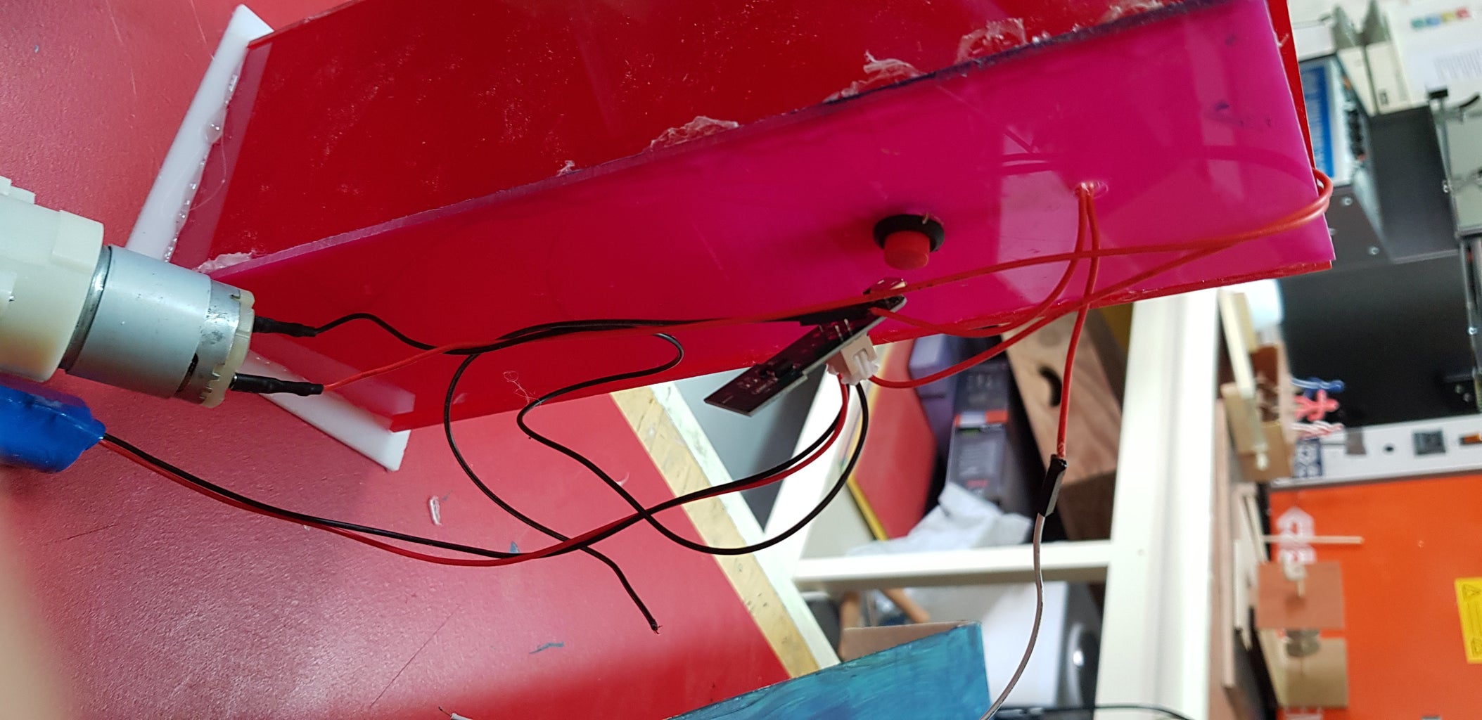
- Drill a hole big enough to fit the first button(this one is used as an emergency button for the water pump to activate.
- Drill a smaller hole on top to fit the two cables from the second button (ones going to the relay)
- Remove the cables from the first button and fit it tightly in the side
Part Three
- Stick all of the sides together except for the bottom using a glue gun to make it semi water resistant.
- Stick the bottom using a glue gun but leave spaces between each line of glue so that the water can come out if the bottle leaks and you can replace it
Part Four
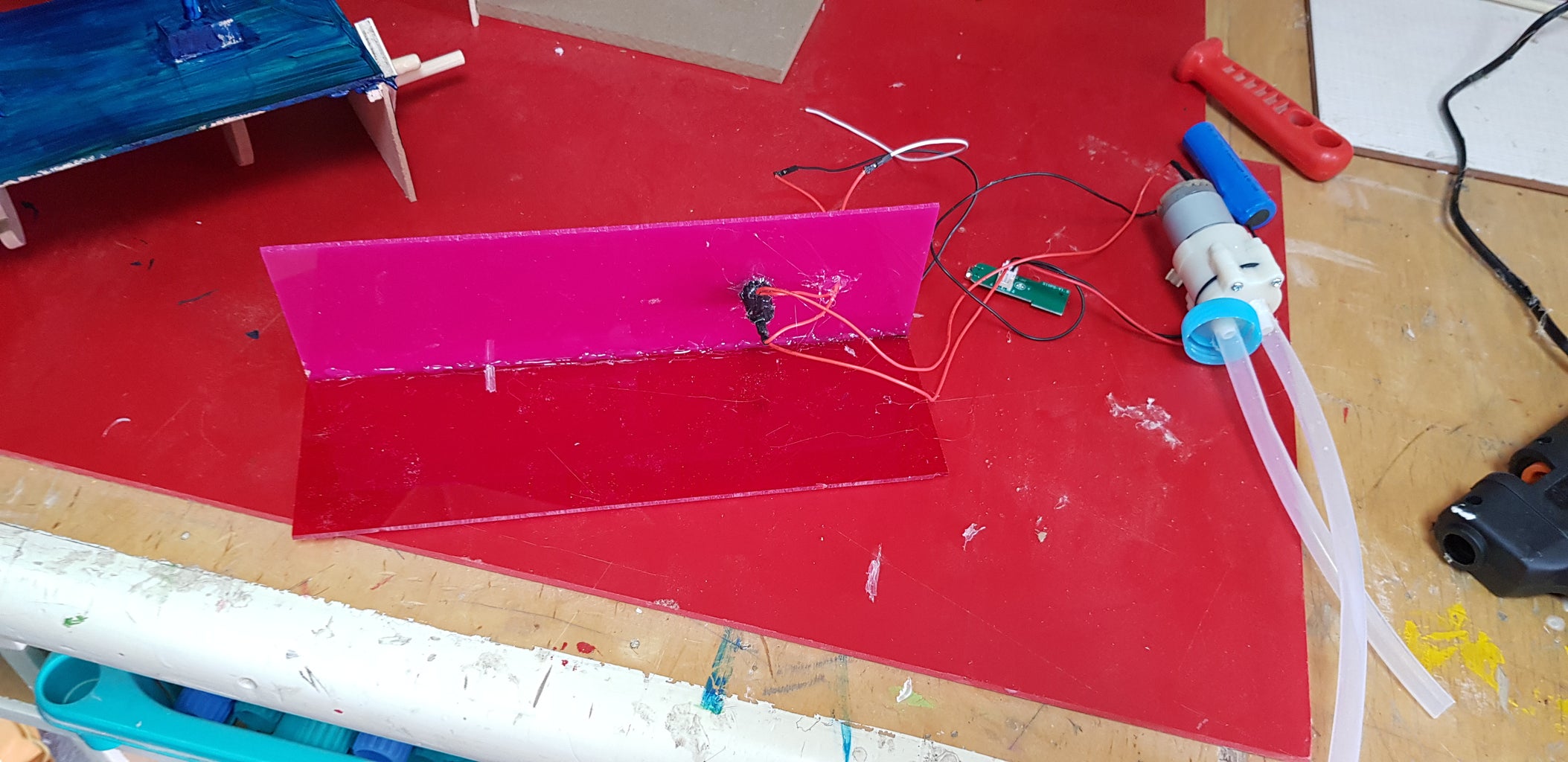
- drill a hole in the water bottle cap and fit the IN tube that is connected to the water pump. If the tube doesn't reach the bottom replace it with some of the extra tubings and cut it to make it the perfect size.
- once it is the perfect size make sure the OUT tube is long if not replace it with the extra tubings.
- once everything is perfect glue gun the IN tube into the water bottle CAP.
- Place all of the parts in the box making the OUT tube come out of the top.
- Attach female to Male jumper cables to the cables coming out of the top hole making it long enough to reach the relay hole.
Step 10: Last Step! Final Connection
- Remove the Male parts from the cables which are meant to go to the relay and connect that cable to the relay. Use a screwdriver to tighten the cables in place
- (if necessary add the 9v connection cable)
Step 11: CONGRATULATIONS!
CONGRATULATIONS!!
You have now successfully made this project. You may now place it wherever you like using different mounting techniques. The last step is to connect the USB cable and/or add a 9v battery if you chose to.