Introduction: DYS ELF Quad-copter Receiver Modification


As this is a extremely simplified example of installing a FlySky FS-A8S Receiver to the lovely DYS Elf quad-copter please ensure you have sufficient knowledge to configure Beta flight correctly in order to use your new receiver and FlySky transmitter to their full potential.
Now to the fun bit!
Tools required to complete this modification:
00 Philips screwdriver
Soldering Iron (Of your choice however I would advise low wattage).
Solder (Preferably a nice resin core electronics fine solder).
Spare JST connector (however you may be able to use the stock one).
Patience...
Step 1: Most Importantly

Please before proceeding any further remove the battery.
Without doing this you run the risk of destroying your flight controller, and because everything on the DYS Elf is integral that means you've basically created a really cool paperweight. :p
Step 2: The Completed Modification Presentation


When complete the DYS Elf looks very clean, with only a small receiver antenna protruding from the rear of the top shell.
This antenna orientation is the best (In my opinion) for signal quality at this level.
Step 3: The Internal PCB and Components

Highlighted in Red are:
Center cover: FlySky FS-A8S Receiver, (Already mounted using double sided foam tape).
Left: Receiver JST connector to PCB.
Right upper: VTX JST connector.
Right lower: VTX JST PCB Female connector.
Step 4: Closeup of the Receiver

The FlySky FS-A8S Receiver mounted and wired to the JST connector and ready for usage!
Please note the binding process is simple however because the receiver does not have a unique radio identifier you will need to power cycle your transmitter (In my case a FlySky i6s) in order to complete the binding process.
You will not receive vital receiver telemetry information using this receiver (i.e RX voltage, etc..) , however as long as the receiver LED status light is constant you should be OK and everything else should in theory operate fine!
You will most likely need to solder the stock JST cable removed from the original receiver to the new FS-A8S receiver.
the pins required:
POWER - Red Wire
GROUND - Black Wire
SIGNAL - White Wire (Note this uses the i-bus communication protocol).
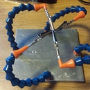
You can use a small tip soldering iron to create a tiny hole to allow for proper antenna position for the receiver.
Super Simple!
Step 5: Conclusion

Please consult Google, YouTube, or forums if you need help in these areas:
Soldering
Finding relevant documentation
Beta Flight configuration
Etc...
or send me a message and I will try my best :)


