Introduction: Darth Vader Robot
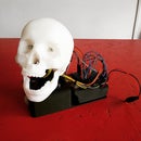
In this Instructable Im going to show you how I made my 3D Printed Darth Vader Head robot using the MakerClub Hornet board and development environment.
The robots head can move side to side and you can change the intensity of the LED eyes using your phone as a remote via bluetooth.
Step 1: What You Will Need
Before we start you are going to need a few things to make this project.
- 1x MakerClub hornet board (you can get one here: https://makerclub.org/product/the-hornet-board/ )
- 1x Tower Pro Servo
- 2x LED's
- 6x Female to female jumper wires
- 2x 100 ohm resisters
- 1x Battery pack x 4 aa
- 4x aa batteries
- 1x Micro USB cable (Mine came with the MakerClub Hornet Board)
- 1x Digital calipers (makes measuring easier but you could use a ruler)
- 1x PVC cement or other glue for fixing the 3dprinted parts together
- 1x 3D Printer. (if you don't have one you could use 3Dhubs.org)
Optional if you want to tidy up your prints:
- 1x Airbrush & compressor
- 1x Polyfilla to fill in the gaps
- some sand paper to sand it down
- airbrush primer paint
- airbrush black gloss paint
Step 2: 3D Print the Darth Vader Head
I used this Darth Vader Head file that I found on thingiverse. http://www.thingiverse.com/thing:1218749 uploaded by the user: nakwada
I managed to fit all the parts into one print and I would suggest you try this too as the print will end up being much quicker.
Step 3: Model the Base With OnShape
This guide isn't intended to show you how to model anything in CAD software. There are plenty of tutorials on Instructables and youtube already so I have attached the file for the base but if you would like to make your own head over to www.onshape.com and register for a free account. Onshape is a professional quality CAD software within a browser with free accounts. Think a lightweight stripped back Solidworks.
You can make the base however you like but it would be wise to use the digital calipers when measuring the servo. Another important thing to take into account is the printer tolerances and factor those into your design. I tend to make things half a mm larger than they need to be else it's often very tricky to fit the servo in.
Attachments
Step 4: Assemble the Print
Once all the parts have printed use the PVC Cement to fix the parts together.
Be careful when using this glue as it smells pretty nasty and is probably not good for your lungs.
You may need to hold the parts together for a minute or two until the bond is formed.
Step 5: Drill the Holes for the Eyes
Once you are sure that the parts have all been bonded firmly together carefully drill a hole through each eye and out the back of the head.
Use a drill bit that is just slightly wider than your LED's so that you can push the LED's into the eye sockets.
Step 6: Optional: Tidy Up the Print
Using the polyfilla, fill in any gaps between the 3D Printed parts, this stuff is pretty easy to sand down so don't worry about it looking messy at the moment.
Once all the gaps are filled leave to dry. Look at the product instructions for how long to leave it.
Once the filla has dried. Use a high grit sandpaper such as 1200 and above to sand down Darth's head. You can also sand down the plastic if you want a smoother finish as the design is pretty low poly.
When you have finished sanding make sure you wipe off any of the dust else the paint won't stick
Step 7: Optional: Paint Darth
As mentioned in the previous step. Make sure that you remove any dust from the part else the paint will not stick and will have a poor finish.
Following the instructions on the primer spray a thin coat over the whole model, leave to dry then repeat again.
Once the second layer of primer has dried use a very high grit sand paper to remove any bumps and smooth the part again.
Finally after removing the dust again following the instructions on the paint spray 3 thin layers of gloss black paint. Allowing it to dry between each coat.
You could also spray a couple of layers of clear lacquer if you want but I decided not to.
Step 8: Assemble the Robot
Now that Darth has been painted thread 4 of the wires through the eyes. Try and use two different colours so that you can tell the difference between positive and negative.
attach the LEDs to the wires by pushing their legs into the hole on the female jumper wires. The long LED leg is the positive and short is negative. Then push the LED's into the eye sockets. If you used the correct drill bit this should be nice snug fit. If not perhaps use some glue or blue tack to hold them in place.
Next take the 2 resistors and attach one to the other end of each positive wires. Finally take the remaining female jumper cables and push onto the other end of the resistors. You should now have 4 wires (2 coming off each led) with a resistor attached to the positive wires.
Next take the negative wire of one LED and plug it into the hornet board by pushing the wire onto Pin 2 BLACK. Then take the positive of the same LED and plugin it into Pin 2 WHITE.
Do the same with the other LED but this time use Pin 3.
Next put the servo motor into the 3d printed base with the wire threaded through the slot. Plug the servo into the hornet pin 1 brown wire is negative so goes on the black pin. red goes to red and yellow goes to white.
Attach the servo horn to the servo using a screw then super glue it to the darth 3d print.
The darth head should now be secured to the base via the servo and all wires should be plugged into something.
Step 9: Program the Hornet Board
Head to www.makerclub.org and signup for a free account. After logging in you will be on your makerclub dashboard. Click the projects tab and then the plus button to create a new project.
Important: Before connecting the Hornet board make sure you have installed the Drivers & Chrome plugin from the makerclub site to be able to use the board with the development environment. You can install them from here if you haven't already: https://makerclub.org/install/
Then click the icon circled in image 3. This will switch the screen from the default text edit view to a drag and drop interface.
Recreate image 4 in your code.
Essentially the code starts in the setup part of the code by telling bluetooth to start. This is because we want to control the Darth robot using the mobile app which uses bluetooth. Then we tell the board to use LED's on Pins 2 and 3.
Then in the loop part of the code (Loop is the part of the code that repeats over and over) we use debug log to say that the loop has started. This just tells us each time the loop starts.
Then we check for a message from bluetooth. If there is we first debug log the message from 1 and 2. 1 & 2 refer to the joysticks in the app.
We then take the value from bluetooth 1 and use it to set the servo postion.
We then do the same with each LED using bluetooth 2.
The loop then starts again looking for a new message allowing you to control the lights and motor in the robot.
Step 10: Build and Test the Code
Connect the Hornet board to your computer via the micro USB it should display in on the MakerClub code editor (See the first pic circled red). It will say something like Hornet1.
If yours doesn't display. Check that you have correctly installed the drivers and plugin. If it's still not showing try restarting your computer.
Next click the blue play button to build your code to the Hornet board.
Note: Do not unplug your hornet board whilst it is communicating with your computer. You must click the eject button before removing it or the USB port may become disabled. Don't worry if it does become disabled as a simple restart of your computer will definitely fix it. I believe this is an issue with how Google Chrome communicates with USB Ports and not the Hornet Board.
You should see an LED on the hornet board flash and a blue progress bar show on the makerclub code platform. Once the bar is filled the program will be running on the Hornet board
Step 11: Setting Up the Controls in the IOS App
First thing is to download the iphone/ipad app here: https://itunes.apple.com/gb/app/makerclub/id106147... or search for makerclub on the app store.
Once installed click "new project" to create a new project. Give it a memorable name and then select the vehicle control layout.
Power up the hornet board by connecting the battery pack and turn bluetooth on your phone on.
If the board and bluetooth are both on then the app should connect to the board automatically. If not click "Scan again".
Step 12: Using the MakerClub Mobile App to Control It
Move the thumb controls about and watch your Robot Darth Vader rotate and eyes light up.
Congratulations on completing the project! I hope you enjoyed it.
There are so many ways this project could be expanded and with all the inputs/outputs on the hornet board you could create some really complex animatronics.
I would love to see what you guys do. So please do post links to your own projects in the comments below!

Participated in the
LED Contest

Participated in the
Circuits Contest 2016


