

Introduction: Designing Our FTC Bot 2023-2024


Note before starting: If any of the CAD embeds in any of the steps show an error, try to reload it until it works. Apparently it has been showing those errors for a lot of my designs and I cannot find a way around it. Worst comes to worst, just click on Open in Fusion 360 to open it in a new tab/fusion app.
Hey there everyone! I'm Ashar, a junior at Harmony School of Innovation- Sugar Land, and I am part of Team Mustangs - #10354. The robot you see above is our work in progress for the 2023-2024 FIRST Tech Challenge (FTC) Season, CENTERSTAGE. It's my pride and joy, and while it may not be finished yet, I still want to share what we have and maybe strike an interest in some of y'all about FTC Robotics. But first, a little about our team, and this year's FTC competition.
Our team, Team Mustangs #10354, is based in Sugar Land/Houston, Texas. We are a well-branched team, with many achievements in previous years and connections to our name. There is a picture above of our previous robot, which earned a variety of awards, including:
- 1x Finalist Alliance Captain (2nd Best Robot Game Team)
- 1st Place Motivate Award
- 1st Design Award
- 1st Think Award/
- 4x Winning Alliance Captain/Ally (1st Best Robot Game Team)
- 1st Innovate Award
- And many more... (Not all our trophies are there, but you get the idea... 😊)
We have also become connected teams with many large companies, including Raytheon, Gene HAAS, Sunoco, and many more.
FTC, or FIRST Tech Challenge, is a global robotics competition among middle to high schoolers; every year, there is a different theme and season, which consists of a new game mat and new missions.
This year, CENTERSTAGE, we must score various colored "pixels", or hexagonal-shaped pieces, onto a large "backboard". (The season is art-themed, so this represents making art on a backdrop... you get the gist!
Following a two-minute driving period, we approach a 30-second endgame, in which we must launch paper "drones" and have our robot climb various trusses to score power points.
This season of FTC robotics is one of the more demanding years, especially for a lesser experienced team like us. However, despite the setbacks we've faced, we want to show our robot progress to you all!
The purpose of this instructable is not only to show you all how we designed our robot, but how Fusion 360 played an integral role in the first iterations of our design.
Before starting on this project, I want to give a huge thanks to the entire Mustangs team - especially our building team, who make up the brains and brawn of our team. Sorry in advance if I don't give y'all enough credit - you guys are the best.
Enough ranting, now... let's dive into the progress we've made!
Supplies
The majority of our parts have been sourced from GoBilda, a proud materials provider for FTC robotics. Their parts are quite high quality, but also reasonably expensive. I won't provide every single structure, as there are too many individual pieces to count, but I'll list the major components, such as the control hub, driver and expansion hubs, and major pieces.
Off-the-Shelf Parts List:
1x REV Robotics Control Hub - $350.00 - https://www.revrobotics.com/rev-31-1595/
1x REV Robotics Expansion Hub - $250.00 - https://www.revrobotics.com/rev-31-1153/
- The Control and Expansion Hub is where all your programs and core information will be stored, as well as where all your wiring is connected to.
6x GoBilda Yellow Jacket 19:2:1 Gear Motors (Planetary, REX Bore) - $42.99/pc - https://www.gobilda.com/5203-series-yellow-jacket-planetary-gear-motor-19-2-1-ratio-24mm-length-8mm-rex-shaft-312-rpm-3-3-5v-encoder/
6x GoBilda Yellow Jacket 5:2:1 Gear Motors (Planetary, REX Bore) - $42.99/pc - https://www.gobilda.com/5203-series-yellow-jacket-planetary-gear-motor-5-2-1-ratio-24mm-length-8mm-rex-shaft-1150-rpm-3-3-5v-encoder/
- These DC motors work beautifully under heavy loads but make sure you choose the right torque and ratios.
GoBilda Servos (Torque and Speed) - $31.99 - https://www.gobilda.com/standard-size-servos/
- Servos are important for smaller attachments, such as a claw or smaller rollers.
12x Encoder Extension Cable - $2.99/pc - https://www.gobilda.com/encoder-cable-extension-4-pos-jst-xh-300mm-length/
- While the drive motors have built-in encoders, it is important to purchase extensions for the motors in order to connect the drive encoders to the hubs.
GoBilda U-Channel 1120 Series - Price Varies on Size - https://www.gobilda.com/1120-series-u-channel/
- This link takes you to their U-channel page, where they have various sizes. This composes about half of our structure. They may be a little expensive, but the investment is worth it for us! Many of our channels are still going strong after 2-3 years.
Misumi Telescopic Rails - Price ranges from $12.99 to $22.99 - https://us.misumi-ec.com/vona2/detail/110300072130/
- We recommend Misumi telescopic rails for extension attachments, such as our extension arm. It is more of a DIY approach than other extendo rails such as GoBilda's, but with the high-quality build, it is COMPLETELY worth it in the long run.
96mm Mecanum Wheels (4-Set) - $169.99 - https://www.gobilda.com/96mm-mecanum-wheel-set-70a-durometer-bearing-supported-rollers/
- Okay, I'll admit, $170 is A LOT for 4 mecanum wheels. However, you can use any wheelset as you'd please, as you can find sets for as low as 30 or 40 bucks on Amazon or any wholesaler.
Screws and Fasteners - I'd recommend purchasing from GoBilda to keep the compatibility, but you can use any M4 set screws. Please ensure you are using M4, as all of these parts are based on M4 compatibility.
Custom Parts:
Now approaching the topic of custom parts: for the most part, I used 3D printing to create parts such as telescopic slide inserts, ramps, and more, but you can CNC or laser-cut these as you prefer.
For 3D printing, I recommend a PLA-based material for the majority of your prints, unless you have a high-impact scenario. PETG or ABS will work well in these cases.
3D Printing PLA Filament Overture - $17.99/KG - https://www.amazon.com/OVERTURE-Filament-Consumables-Dimensional-Accuracy/dp/B07PGY2JP1/ref=sr_1_4?crid=3TAD0QT7R75E3&keywords=pla&qid=1699764288&sprefix=pl%2Caps%2C116&sr=8-4
Tools and Software:
I must admit here, I am not much of a software guy - I always had trouble learning software, and stuck with CAD as my lingo. However, I will still list software components to the best of my ability - apologize in advance if I miss anything.
CAD: For the majority of this project, I utilized Fusion 360, an amazing tool to design all our components and assemble the robot in advance.
3D Printer: I would recommend a 3D printer with a bed size of at least 250mm x 250mm x 250mm. My Ender 3 Pro works amazing for this project, and if you want to make specialized parts (sorry - WHEN you need to make them... making custom parts are important), I'd recommend a decently sized printer.
Android Studio - When coding the robot, you want to have a good coding studio, as you'll be making project after project of heavy coding, image recognition, tesselation analysis, odometry, and so much more.
Allen Keys - Hex tools/Allen keys are crucial for these parts, as they come majority with hex head screws.
Hammer - You'll need a hammer to smash things in place :)
Filer/Sanding tool - This will come in handy for fixing the tolerances of your prints. Trust me when I say that shaving off a layer or two might come in handy, so have some sandpaper lying around!
Safety:
I cannot emphasize enough how important safety is! From inhaling metal dust to laser cutting fumes to sawing polycarbonate, each and every action you complete has a risk in the lab. Here are a few things to remember at all times:
- Work in a well-ventilated area! Keep a window open, or have a vent pumping fresh air into your workspace, such as an AC or a fan.
- When cutting things, such as aluminum or polycarbonate, both of which can emit dangerous particles or gas, it is ideal to have a vacuum pump or vent running into the cutting machine. A mask can also suffice in case you don't have a pump machine.
- Safety goggles and gloves are a MUST when working with parts!
There may be a lot to take in with this list of parts and actions, but it is important to keep all of this in mind; rather than this being a single, two to three-month-long project, this is a years-long project that can be worked on as a team. With the right funding and time set aside, you can create something truly amazing.
Without further ado, let's jump into making the bot!
Step 1: Analyzing the Season's Game/Planning Your Design

Each season of the FIRST Tech Challenge, a new game mat is released. Additionally, it is important to remember that each round, 2:30 long, consists of two "alliances" of two teams each, each presenting one robot. One is the Red Alliance, on the left side of the field, and another is the Blue Alliance, on the right side. Each one will have to take the missions with slightly different positions and methods, so this is important to consider when making the first iteration.
This season of CENTERSTAGE, we are met with the following missions:
- One backdrop per alliance, upon which you place different colored "pixels" in formations of three; this creates a "mosaic". This is the main point of the game and lasts the entire match.
- Various trusses cover the middle of the mat, which will be climbed upon the "end game" phase (the last 30 seconds).
- Launching a paper "drone" or airplane over a truss
Taking into consideration the missions required to earn points, we can then begin sketching out our first robot design, or designing it in CAD!
There are some amazing resources available online to help you design the basic components, such as a drive base, a swivel, the intake system (which I am using), and much more.
FTC Community Site: https://gm0.org/en/latest/docs/appendix/gallery.html
- This website has categories to look into various mechanisms, as mentioned above.
Example CAD: https://cad.onshape.com/documents/ecc71c6b26b43f044d4b2589/w/a43082b1875fd38bd5f9bcd2/e/83bd8eba2133596a2717cfac
- This is the robot from last year we contributed to and has some mechanisms we will use this year.
Before jumping into concepts and designing, it's important to note down some of the constraints as outlined by the FTC rulebook:
- The robot must remain under an 18in x 18in x 18in size constraint before initialization. This means that after the game starts, your robot can expand as you please. (Don't have the robot open over half the field, though...)
As the lead designer and a builder on our team, I'll be going into strictly the mechanisms, particularly...
- The Drivebase
- Linear Slides/Extension
- Intake Mechanisms
1. When designing the drive base, it's important to consider three main aspects of the drive base:
- The thickness of each side, as it contributes to how much of your mechanisms you can fit on the inside of the robot.
- What wheel systems you will be using? It can range from a butterfly drive, to a 6-wheel traction pushbot, to mecanum drive, to an omniwheel drive.
- Whether you want to have a belt-driven/chain-driven system or a direct-drive system.
For this year, we chose to have a direct-drive mecanum drive base. Having mecanum wheels provides for a great range of motion, as well as strong traction for speed even with heavy weights. Choosing a direct drive system can be good for faster speeds, although a belt drive will give you similar speeds.
- We learned that choosing a belt drive is better when choosing to build a parallel plate drivetrain, which is usually custom-built. These are great for aesthetics, as well as conserving space, as you can fit your motors right next to the wheels and pulleys/belts. Here is an example of a parallel-plate system.

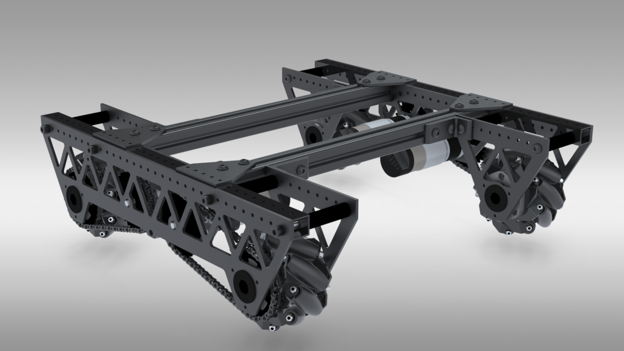
Our amazing build team (love you guys 😍) decided that we might do a parallel plate drivetrain after league competitions. I've attached the CAD of our take on a parallel plate DT at the bottom!
Once our team analyzed the game, we decided to implement a rotating arm in between two linear slides, in order to reach higher points on the backdrop and score more pixels.

In order to take in the pixels and place them into our "carriage", or the little box on the end of our arm, we need an intake system that can rapidly suck in pixels and accurately place them into the deposit mechanism.
I decided that a system of surgical tubing placed on rotation pieces on axles at the back of our robot would work sufficiently to take in pixels at a fast pace.
Now that we have conceptualized what attachments we want to implement into our robot, it's time to move on to designing custom parts that we need to assemble each mechanism and put them together into a tangible bot!
Full Drivetrain Connected
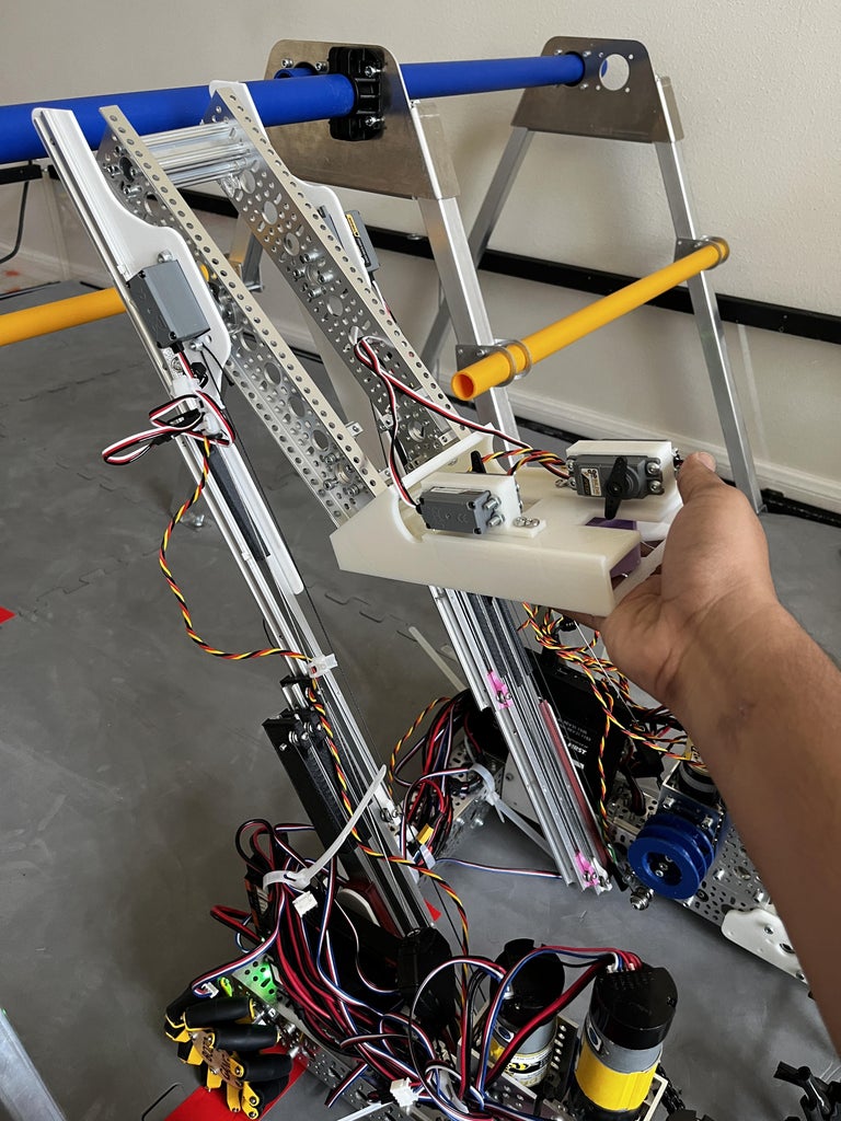
Step 2: Creating the Linear Rails
One of the most important subassemblies within our robot design is the linear rail assembly. This will allow our outtake to extend to higher spots, allowing us to drop pixels at the ideal spot.
We used Misumi SAR230s, a quality Japanese drawer slide that many teams use for reliability and strength.
While these slides are popular among more experienced teams, you are required to create your own "inserts" (connection pieces) in order to connect two slides together. I 3D modeled and printed these inserts using PLA+.
In order to retract and extend these slides, you need to install bearings into the inserts and drive them using string. I recommend a string or fishing line with a strength of at least 150lb rating.
Once we are able to connect the slides, we need to design plates to connect the subassemblies to:
1) The drive base, and
2) The middle outtake assembly.
For prototyping purposes, I used cast white acrylic panels, as it is cheap and easy to laser cut. However, I recommend polycarbonate or aluminum (must use CNC) for a competition-level finish, as these are much stronger and can withstand longer stress loads.
Once we have completed the basic structure of the linear rail assembly, we need to consider what motors to use in driving these rails up and down. Some things to consider:
- The motor needs to have a sufficient gear ratio that can create a stable and medium-speed consistency in extending and retracting the slides.
- It needs to be powerful enough to drive a heavy load, depending on what we are lifting.
- We need to prevent burnout and overheating of the motor, as it was a common problem last year.
Taking into consideration these points, we settled on a 13:7:1 Ratio Planetary Gear Motor from GoBilda, sporting a 435 RPM speed and an 18.7 kg/cm weight load rating. This motor provides a strong and stable drive, being able to support heavy weights while extending and retracting at reasonably high speeds.
Once we have completed the assembly of our linear rail drive assemblies, we can begin mounting our first subassembly on the robot!
- I have attached CAD representations of all our subassemblies and stages of the robot beneath the step, and this is done after each main step.
SAR230 Misumi 4Stage Assembly
Stage 1
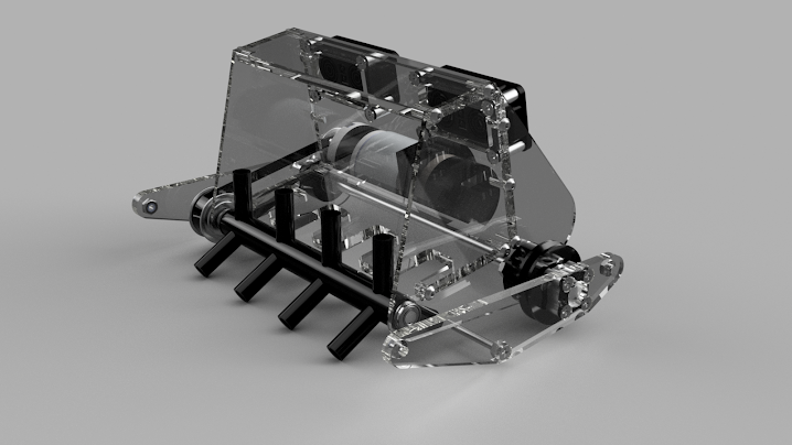
Step 3: Creating the Intake
In order to gain possession of pixels during the game, our robot needs a way to intake the pixels into a chamber, claw, etc. There are a few methods of intake:
- Active intake - Constantly running rollers or tubing to grab anything in the path of the intake
- Claw intake - As the name says, it's simply a claw(s) that will grab onto an object.
- Passive intake - A stationary intake system, such as a stationary mold that will wrap around an object upon contact.
Because FTC games are all about speed and accuracy, I decided to choose an active intake, particularly one made of 3D-printed rollers with surgical tubing attached to it.
- We chose 70A durometer tubing, purchased from McMaster Carr, giving us the right balance of strength and flexibility.
Choosing an active intake allows us to constantly run the intake throughout the match, letting us grab a pixel in a split second. The surgical tubing also gives us additional grip and range, allowing us to have even more security in our possession. These are all advantages over a claw or passive intake, both of which need precision in moving and grabbing the object.
An additional point: We initially chose to use a ramp as part of our intake; however, it added extra bulk to the design and took up valuable space from the carriage. Attached is a video of our intake on the ramp. The ramp idea didn't work as well because of the compressed space it was in, and the walls did not guide well.
For driving the active intake rollers, I chose a chain-and-sprocket system, allowing for a smooth, strong, consistent drive.
- With a 1:1, 6000RPM motor, we can achieve INSANE speeds and grab the pixels extremely quickly.
For now, our intake is stationary, in the sense that it lies only at one height. In the future, we are planning to implement a servo system to be able to lift the intake up and down to accommodate for different sized objects and stacks of pixels.
intake roller assem
Stage 2
Step 4: Creating the Outtake/Carriage
The final main subassembly of our robot is the carriage, or the outtake system.
With the carriage, we can take the pixels through our intake, and carry it up towards our deposit area.
When designing the carriage system, we need to take into consideration some key points:
- Consider how you will control the individual pixels when dropping them out of the carriage.
- How will you orient the carriage to have the intake deposit pixels into the carriage, and then reorient it so it can deposit pixels onto the backdrop?
- What kind of servos will you use for both controlling pixels, and changing the position of the carriage?
These points should always be in mind when designing the carriage, or whatever outtake system one would create in this situation.
When I was designing our carriage, I found it to be one of the more foundational aspects of our overall robot design, as each of the other subassemblies relied on the shape and functionality of the carriage in order for the others to work. Initially, I had planned for a ramp to intake our pixels; however, with the size of the carriage, it was far too tight of a fit, and I removed the ramp in order to create more room for error and adjustment. Additionally, I had to redo the slides and their inserts a few times in order to mold them around the shape of the carriage just right.
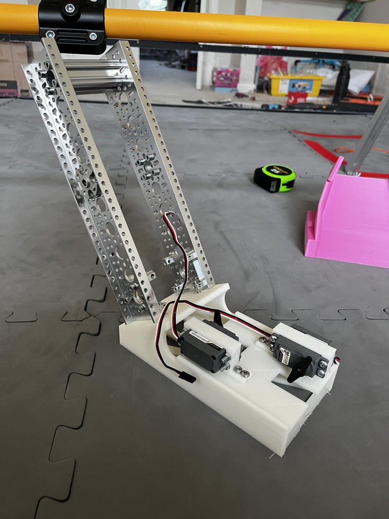
For the general shape of the carriage, we wanted to create an arm-like base at the back of the main carriage, in order to create a larger swivel point and to have greater reach when depositing the pixels. I utilized a few metal plates and channels in order to create this arm, creating a stable yet smooth rotating arm.
- This metal arm is what connects to the pivoting mechanism in between the linear rails.
For the actual carriage portion of the subassembly, I 3D printed a sort of box-like structure, with chamfered edges to allow easy entry of the pixels.
- I added pocketing at the bottom so that our drivers can see what color pixels are inside the box, as it is surrounded from all four sides and it is important for the drivers to see the color of each pixel in order to score accordingly.
- I split the design into multiple pieces for ease of printing; you can choose as you'd like, however.
To control depositing the pixels, I mounted two servos on the top, one to grab onto each pixel. This is done through a small plastic finger that is attached to the servo gear.
Now the final aspect of this subassembly: is the pivoting mechanism. When we are rotating the arm from the intake area to the backdrop area, we need:
- Speed, as we need to extend or retract at a moment's notice
- Stability, as we will often be extending this arm after extending the linear rails; we do not want to disbalance the robot in any way or burn out the servos.
Both of these things can be easily accomplished using the right servos. When calculating the weight of the overall arm/carriage, and the torque that would be needed to rotate the arm around 60 degrees back and forth, we decided on a Torque 300 oz-in (21.6 kg. cm) servo(s) from GoBilda. We attached one servo to each of the linear slide assemblies, as seen in the previous CAD models, and we're good to go!
Pixel Armsssssssssssssssssssssssssssssssssssssssssssssssssss
side and arm
Robot Drivebase V3
Step 5: Using Fusion 360 to Assemble/simulate
Once we had finished custom designing our parts, we utilized the various assembly functions of Fusion 360 to assemble our robot's first iteration virtually, and "simulate" the different mechanisms to see how they would work in real life.
- Please note, whenever I say simulate, I mean a much more simplified range of motions, restricted by some functions, etc. I am still learning my way around F3D, but I'm using the various beginner functions to test what I can! 😊😊
Because of my relatively new experience with Fusion 360, I decided to go towards the more "scuffed" method of assembling the parts, which is to say using a Rigid Group and Aligning all the parts to perfection. 👌👌
- While I was able to learn about joints later on, using Rigid Group and Align functions allowed me to put together the first iteration of our robot, and let our team understand how this bot would come together.
Using Joints, including As-Built Joints and Motion Links, allowed our team to delve deeper into simulating the motion of each subassembly.
- Attached above is a (silent) clip of how I used these functions to simulate a dual-pixel claw I helped to design, which our junior team will be using this year.
Furthermore, using the various assembly functions allowed us to create sketches of our robot and subassemblies, which are going to be immensely useful in our competition interviews with engineers and judges this year.
- During FTC competitions, there is a judge panel who interviews every team. Creating CAD sketches and renders of our designs, no matter how important they are, shows the judges your design process and looks quite impressive once you lay out your plans.
Vertical Claw Solver Time GB
Step 6: Using Fusion360 to Create Sketches


As I mentioned above, during the judging phase of an FTC competition, it's extremely important to show the judges proof of progression and proof of concept of your designs. This can be through renders, sketches, and more. I prefer to use Autodesk-generated sketches, as these look quite professional, are relatively easy to develop, and can be made to fit into a design portfolio for the judges to marvel at.
I am pretty new to sketching in Fusion 360, as I am more accustomed to Inventor sketching; while they are moth similar, the change in UI and performance/functionality has tripped me up just a little. I will just show some examples of sketches I have generated using Fusion 360, in order to show how good these sketches can be at conveying basic principles of your design.
Step 7: 3D Printing the Parts


Ahh, now comes the fun part: 3D printing all our custom parts and getting ready to assemble the real deal! It's pretty simple, considering that 3D printing has come so far and become so easy to use nowadays.
The filaments we used are:
- PLA and PLA+ for all our basic designs and low-stress parts, such as our carriage.
- ABS and ECO-ABS (Dremel brand) for our higher strength and more resistant parts, such as our linear rail connectors.
- PETG in similar use cases like ABS.
The 3D printing aspect of my project is quite straightforward; however, there are a few things to keep in mind when slicing or touching up the designs:
- For structural parts or high-stress parts, I would recommend at least 4-5 walls, as more walls are generally better than a much higher infill.
- Of course, increase the infill to around 25-35% while increasing the walls if you are printing a strong part.
- For the majority of these parts, I did not need support, as I kept in mind to keep a reasonable angle across all non-flat parts of the file. However, if you do need to print supports, I would recommend keeping the density low, as many of the custom parts teams use need good detail quality.
- Because I needed rapid prototyping, I used layer heights ranging from 0.2-0.3mm, because my Ender 3 Pro prints slower. However, this layer height is good enough for most structural parts.
Attached above are some of the MANY prints I have done over the season...
Step 8: Assembling Our First Robot

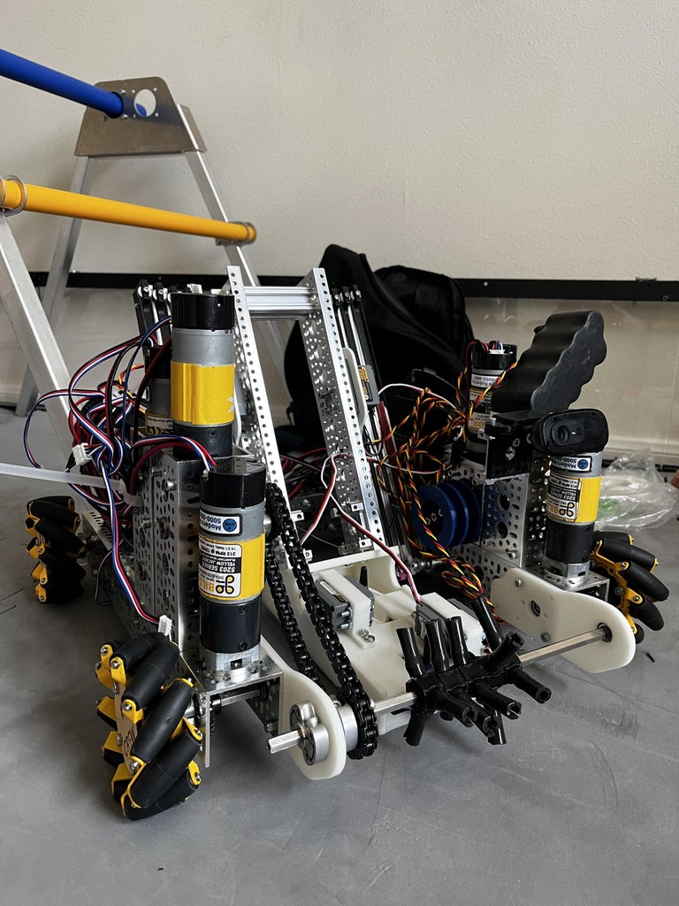


Now comes one of the more exciting parts of our FTC journey: Assembling the first iteration of our robot! In this step, I will cover the basics of our process, and mainly important aspects of the design process that other teams can take into practice, rather than list out every step. This is so other teams can take inspiration from this and create their own ideas.
- We began with assembling the robot drivebase. This was essentially connecting multiple metal bars and channels to create a sturdy base, and routing motors into the base to run a direct-drive system. We then attached the mecanum wheels to a set of miter gears, allowing us to tuck the motors into little metal pockets and keep them out of the way.
- One important thing to keep in mind is that when creating the drive, you should make sure to have enough support to withstand heavy loads and stress over time. We have suffered from a similar issue, where our robot is too heavy and creates sagging while running during a game.
- Once we finish with the basic drive base, we attach the side plates and mount our linear slide subassemblies onto these plates. We lead some kevlar-grade string through the bearing inserts and tie off these string snippets through some spools attached to heavy torque motors on the side. This is to drive our extensions and retraction strings for the lifts.
- When routing the retraction string and extension string, I recommend tying off the retraction string at a lower point without a spring in order to have a more stable retraction drive. We used to use a spring, but it constantly bent and deformed under the loads of a heavy lift.
- Creating the intake is one of the easier parts of this assembly. Simply attach the intake panels to the sides of the robot, and push one axle of your choosing (we used 250mm) through both plates, and add some bearings for a smooth rotation. Round some chains around the sprockets on both the intake motor and the axle, and you're set!
- Finally, the carriage arm. I simply attached some servo hubs to the arm, screwed them onto the servos, and we can call it a day here!
Once again, this step was intended to be a very general overview of our assembly process, and we'd rather teams take inspiration from our design process and create their own robots. To reference any specific assemblies if you are confused about a step, refer back to any of the CAD models I have linked in a specific step beforehand. 😊😊😊
Step 9: Wiring the Control/Expansion Hubs


Wiring the robot as a whole, including the control and expansion hubs may seem like a trivial part of the building process for many people. However, many teams, including our team, have suffered at the hands of weak connections, too tight wire loops, or simply connecting the wrong wire to the wrong port. This step will be a sort of short guide for those who would like some tips on properly wiring their robot and keeping an efficient wire-management system.
First, a guide on the control and expansion hubs.
The control and expansion hubs are the only legal robot controllers/brains in official FTC gameplay and registration. These are manufactured by REV Robotics, so it's great to see that every team uses the same set of robot controllers, allowing for better ease of access and a wider community support base.
The control hub is the main brain of the robot. It is where all the essentials are routed through, and where the main power is received.
- The control hub has the following ports:
- 2 battery ports
- There is one main battery port, where the actual battery connects. The other one is a secondary power port, to which the expansion hub is connected.
- 4 motor ports
- 4 encoder ports
- 6 servo ports
- 2 +5V Power ports
- An array of analog and digital sensor ports
- Some USB ports (2.0, 3.0, Type-C)
- An HDMI port (For all of your "4K/60Hz" needs... 😕)
The expansion hub, as in the name, is an expansion brain for the control hub, providing additional ports for the robot to utilize if the team needs it.
- The expansion hub has almost an identical set of ports, with the only difference being a single power port for the control hub connection.
Attached above is a basic wiring diagram for the Control Hub. Note: The Expansion Hub uses an almost identical wiring setup.
When connecting your main motors and encoders to the robot, it's important to remember that since most FTC legal motors use built-in encoders, REV has placed one encoder port next to each motor port, so you can connect the motor's encoder right next to its power port.
Now comes some of the common problems that teams face:
The first one is managing longer wire connections, especially those that connect to things such as servos at the end of a linear slide assembly (like the ones we have to control our carriage). Teams often suffer from sudden port disconnections when they suffer an impact, or simply extend/retract their assembly too fast for the wires to keep up. To tackle this problem, we have come up with a strange yet surprisingly effective method:
Retracting ID loops!
While it may seem strange, the cheap cost, strong retraction and easy extension, and strong quality of these spools, make for an effective way to manage long lengths of extension wires that are constantly being extended with linear extension assemblies. Simply print a small circle mount to slide these ID loops into, and tie the ends of these strings to the wires you want to keep in check from detaching during a match!
Another point I'd like to mention is to refrain from reversing the polarity of the input DC power. While most recent REV products have implemented reverse polarity protection in their hubs, there is still a strong chance of damaging a product by reversing these ports. Ensure that you have correctly connected the input DC power cords before continuing!
Finally, I want to emphasize how important it is to remove stress from your wire connection ports. Whether it's from one servo extension to another one, or from a motor power line to the control hub, putting strain on these ports and connections can cause some severe damage in the long run. I'd recommend, mainly just for your more important ports such as the battery port and USB hub power port, to make a small connection support piece and attach it to the head of your cable. I attached an example at the top; these little support pieces have saved us so much trouble from frayed heads and torn cables. Additionally, you can also zip tie your cables to prevent knotting and further tension on your cables.
Step 10: Project Checkpoint: Where Are We, and What's in Store?
At last, comes the end of this lengthy instructable. Pretty drawn out for this kind of a project, huh?
I feel like one of the most rewarding parts of an FTC robotics project like this is to simply stand back, and marvel at the result of countless hours' worth of blood, sweat, and tears. It can be extremely challenging to create a robot that has to fit under so many criteria and constraints, and still perform up to a certain standard. However, this is most DEFINITELY not the end of the road for us! In fact, it's only the beginning...
There are so many things that we aim to continue improving throughout this season. I've attached some videos of us demonstrating various subassemblies in our robot. Ranging from driver control to running some of our mechanisms, to getting our autonomous code to work, we have a lot of things that we need to continue working on.
I think that one of the biggest things we need to work on now is adding two new attachments for the bonus missions in the game: a hanging mechanism for the end-game hang mission, and a paper drone launcher for the end-game launch mission. This will be a little difficult, as our robot is already so packed with mechanics, but we always find a way with a little grit!
Extra Note:
- I was initially going to attach separate files to download for each custom part I designed. However, these parts numbered wildly past the tens, and my computer could not handle uploading each file to this instructable. I enabled the download feature on every CAD embed I linked in every step, so if you are interested in downloading and printing any of the files, or making any changes to such, you can simply hit the download button, and select which file type you'd like. (3MF, STL, STEP, etc.)
I will try to update this instructable as we continue to make progress throughout this season.
I saw this competition just a few weeks ago and decided that this would be a great way to show off this project and maybe interest some other people, too.
Anyway, I hope you all enjoyed this lengthy instruction about our robot so far. If you think it's great, drop a favorite so I know there are some people out there interested in FIRST Tech Challenge.
Until next time, cheers!
Runner Up in the
Robotics Contest


