Introduction: ESP01 Programming Printed Circuit Board


Recently, I had to write a code on my ESP01 and decided to use an adapter to transfer the code to the CHIP.
However, it was necessary to make some modifications to the adapter so that the code could be transferred.
That is, the adapter was not entirely ideal for performing code transfer. An adaptation was necessary.
Supplies
- JLCPCB Printed Circuit Board
- 02 x Buttons;
- 01 x 330R resistor;
- 01 x Green LED;
- 02 x 10kR resistors;
- 01 x Male / Female Pin Bar 1x4;
- 01 x 2x4 Female Pin Bar.
Step 1: The Conventional Adapter

The adapter used is shown in the figure above.
However, to avoid problems and make modifications to the structure, we decided to create an adapter, which would be able to work with an ESP01 adapter and perform code transfer to CHIP.
The print circuit board is shown above.
In this article, you will learn how to build your programmer and what are the main parts of the ESP01 flashing circuit.
Through the design of this electronic circuit board, it will not be necessary to make new adaptations and it is able to record the code of your project.
Therefore, in this article you will learn the following points:
- Develop an ESP01 recorder and adapter;
- Understand the purpose of the ESP01 recording circuit;
- Learn how to set up ESP01 for code transfer mode. Now, we will begin the complete presentation of the development of the Programmer project for the ESP01 Board.
Step 2: Developing the Programmer for the ESP01 Board
As previously mentioned, the project consists of creating a programmer for ESP01 in order to facilitate its programming.
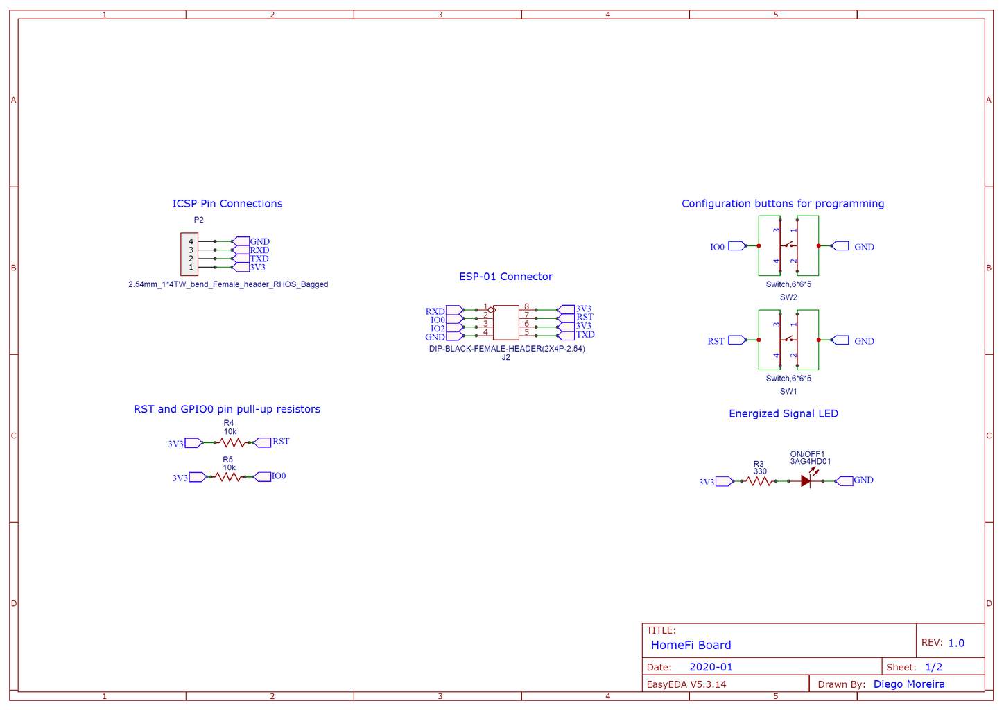
For this, we developed the following circuit shown in the figure above.
Therefore, as you can see, this circuit has:
- 2 buttons to configure ESP01 for programming mode;
- An LED to signal that the card is energized;
- Pin bar for transferring the code to the CHIP.
Below, we present the material needed to build the project.
List of Electronic Components
- JLCPCB Printed Circuit Board (Project Files Download)
- 02 x Buttons;
- 01 x 330R resistor;
- 01 x Green LED;
- 02 x 10kR resistors;
- 01 x Male / Female Pin Bar 1x4;
- 01 x 2x4 Female Pin Bar.
Now, we will explain each part of the ESP01 programming circuit. Note that we use a 2x4 - 2.54mm connector for the ESP01 connection, as shown in the figure above.
From this connector, ESP01 will connect with all other parts of the developed circuit.
Therefore, first, connect it to this connector and set it to programming mode using the RESET and FLASH buttons. These two buttons will be responsible for setting it in programming mode.
Finally, we have the connection pins of the USB - SERIAL FTDI232 converter and the LED. The converter connection bar will be used to connect it and carry out the code transfer to ESP01.
The LED will be used to indicate that the card is powered.
From this circuit, we carried out the design of the electronic board.
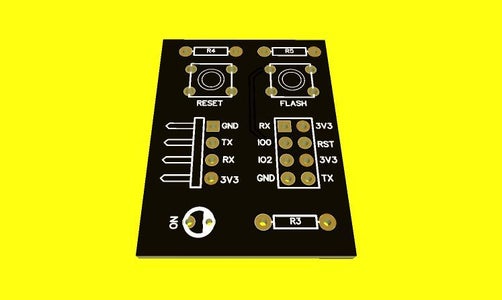
Step 3: ESP01 Programmer Printed Circuit Board Development
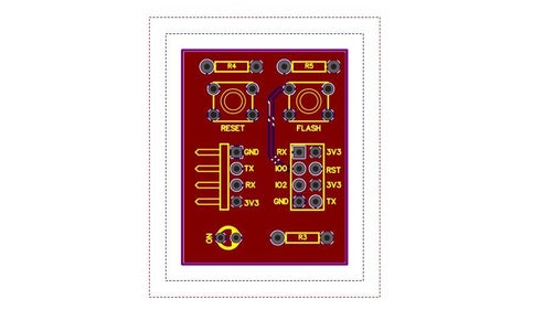
From the design of the electronic schematic design, the ESP01 Programmer's printed circuit board design was developed.
The schematic of the board design is shown above.
As you can see, the ESP01 must be connected to the 2x4 connector and the USB-Serial converter will be connected to the 90º pins.
This connector with the respective angle was used to reduce the size of the board and leave it below the ESP01 structure.
In addition to it, we have the programming buttons at the top and the LED for signaling the energized plate at the bottom of the plate.
From this project, the final printed circuit board in 3D was obtained, which is represented in the figure above.
Finally, from this project, it is possible to carry out the programming and recording of the code in ESP01.
In the following, we will explain the step by step to put ESP01 in programming mode and transfer code to ESP01.
Step 4: Code Transfer Process for ESP01
To do this, you must perform the following steps:
- Connect the USB-SERIAL FTDI232 converter to your computer and to the ICSP Pin Connections bar;
- Check that the LED is on. It is used to indicate that the card is powered;
- Select the COM port of your FTDI232 USB-SERIAL converter;
- Press and hold the FLASH button;
- Press and release the RESET button. After that, you will see the blue ESP LED to flash once.
Ready! Your ESP01 is configured to receive a new code. Now, carry out the process of transferring your code through the Arduino IDE.
After the transfer, your code will be recorded in the ESP01's memory and it will be ready to control your application.
Step 5: And Finally ... What Is the Expected Result?
Therefore, from the development of this project, it was possible to create a card with features superior to the conventional card and which is widely sold in several stores.
Unlike the conventional board, this version has two buttons to configure the CHIP for programming mode, in such a way that it is not necessary to add new elements to perform this task.
Thus, through this project, it was possible to develop a recorder superior to that existing on the market, to understand its configuration operation and to carry out the CHIP configuration process to carry out the code transfer.


