Introduction: ESP8266 Desktop Clock (WiFi Synchronised!)
The ESP8266 is a awesome chip; with integrated WiFi, 80MHz clock speed, total 160kb RAM, 512kb of flash memory, and a ton of other features, it makes a regular Arduino look like a joke. The project shown in this Instructable is based solely on the ESP8266-01 module, unlike several other projects on the web where it is used in tandem with another microcontroller. This makes it great demonstration of the capabilities of the ESP chip.
The desktop clock I made is pretty much bare-bones, but equipped with some interesting features:
- Large LED display showing 24-hour format time
- WiFi updated time: Always accurate!
- Time never needs to be set manually
- Compact, can sit neatly anywhere
- Based solely on the ESP8266 microntroller
- Can be programmed with newer firmware easily
Why the ESP8266?
- The module is really small
- Low power consumption
- Inbuilt WiFi allows it to update time, the same way your phone or computer keeps their clock accurate! (For more on how this works, see this)
Step 1: Project Details...
Cost: ~Rs. 450 (or ~$20 if you were to buy all components from Sparkfun)
Difficulty: 7.5/10 (Intermediate level)
Skills Required:
- PCB Fabrication (if you decide to do it yourself!)
- Soldering
- Familiarity with the ESP8266
Materials:
- ESP8266 -01
- Shift Register 74HC595 x2
- Common Cathode 7 segment displays x4
- BC547 transistors x4
- LM317 IC
- Heatsink for LM317
- Resistors:
- 1K x4
- 100ohm x7
- ~390ohm to 680ohm x1
- 220ohm x1
- 390ohm x1
- 1N4007 diode
- 0.01uF ceramic capacitor
- 100uF capacitor
- Bent male headers
- Female headers
- 1 screw terminal
- Lots of jumper wire
- Translucent paper (or tracing paper)
Prerequisites:
- You should have set up the required software on your computer to program the ESP8266 with the Arduino IDE. Follow this comprehensive guide if you haven't already.
- You'll need something like a USB-to-FTDI converter to program the ESP8266!
Step 2: About the Circuit...
On paper, the ESP8266-01 module only has 2 pins, whereas we need at least 3 for controller the shift registers. The problem was easy to overcome; the TX pin can be used as an output! In my circuit, the ESP controls 2 daisy chained shift registers (learn more on shift registers and how they work).
Shift-Register Wiring:
In my circuit, only two shift registers control 4 7-segment displays, using a handy technique called multiplexing. Multiplexing involves switching on and off each of the 4 displays extremely fast, so that all off them appear to be on to the human eye (see persistence of vision).

The GIF above shows the process of multiplexing in slow motion. Notice now that instead of 28 pins, we only have 7 (a to g) + 4 (cathode of each display = ) 11 pins to control!
Now, shift register A controls pins a to g, while shift register B controls the common cathode pin of each 7seg display. In this way, all outputs are controlled via only 3 pins of the ESP using 2 shift registers.
Step 3: Preparing Your ESP8266
The ESP8266 microcontroller is the heart of the clock. I used the Arduino IDE to directly program the ESP as its the easiest method out there. If you are new to the ESP, follow this comprehensive guide on setting up the required software.
Note: You'll need something like a USB-to-FTDI converter to program the ESP8266!
Step 4: Making the PCB
This PCB was designed on eagle for a single sided PCB, although it the design can be easily tweaked for a double-sided one. I won't go through the PCB fabricating process here, but here are some methods you could try out if not familiar with this process.
Methods for transferring circuit design onto a copper PCB:
- Toner Transfer, using iron (check out this other tutorial too) -I used this method
- Toner transfer, using laminator
- 'Cold' toner transfer
- UV/Light fabrication (using pre-sensitized PCBs)
Methods for Etching PCB:
- Normal Ferric Chloride etchant (try a quick method) - I used this method
- Homemade etchant
Making the Clock PCB
1. Toner Transfer

NOTE: Do not print the mirrored version of the eagle board!!!
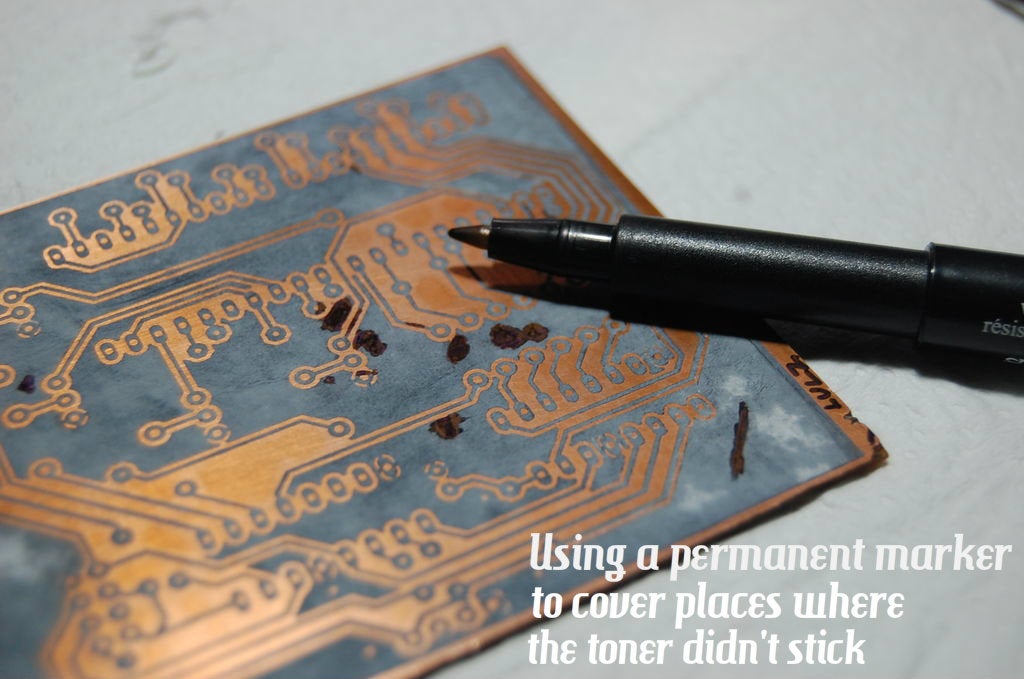
2. Etching the PCB
Materials:
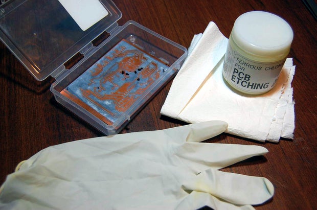

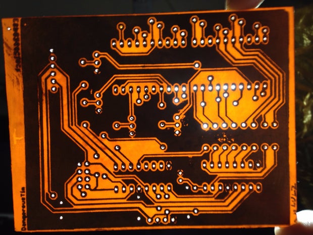
Yay, a completed PCB board! Oh wait we gotta drill holes too...
3. Drilled PCB
Of course you can use a drill or drill press if you have one. I wasn't willing to spend much on a new drill, so instead I settled for a sweet little pcb drilling motor, powered by my benchtop 12V supply. With that I made a bare-bones drill press, see the picture above!
PS: Download the eagle files below!
Step 5: Populate the PCB
Yes, the PCB turned out to be a fine piece of art, but now you've got to stop admiring and start ruining it by soldering.
1. Start with the 7seg displays, but remember to solder in the jumper wire that hides beneath them before!

2. Next, the resistors...
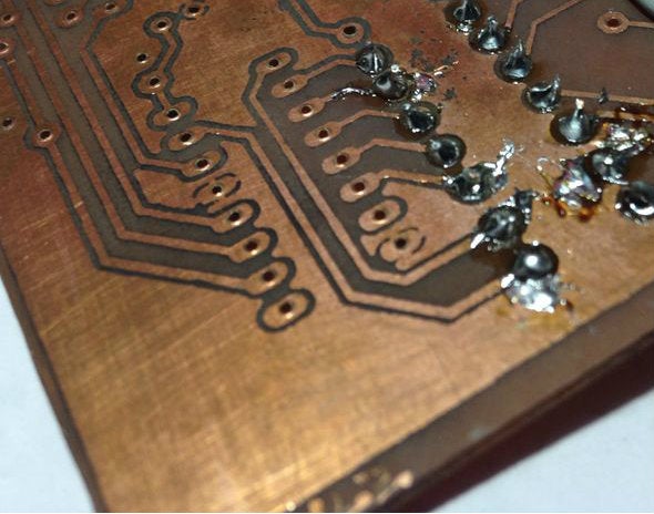
I know I did a messy job, but oh well the connections work. Use a multimeter!
3. Now solder in the jumper wires close to the displays...

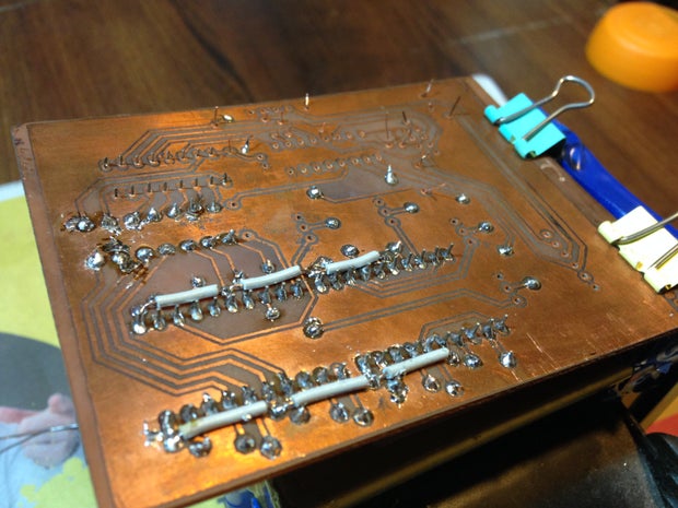
NOTE: I soldered the jumpers closest to the displays on the copper side, due to space constraints.
Step 6: Soldering in the Rest of the Components...
4. Place the rest of the jumper wires and solder...
5. Solder transistors. Be careful, they are a little sensitive to heat!

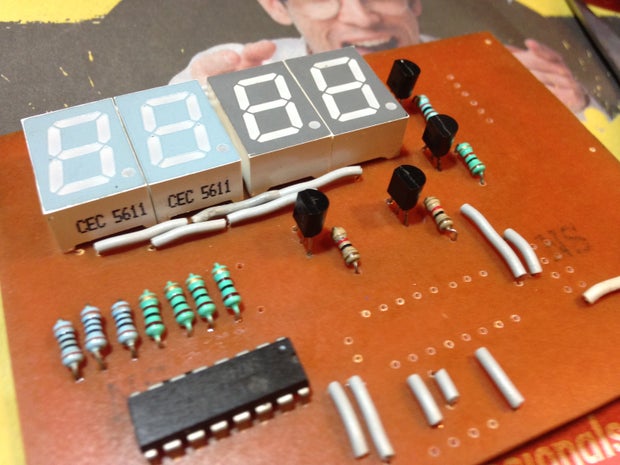
The above image shows the jumpers and transistors soldered. Observe the correct placement of the transistor! Note that the IC hasn't been soldered yet...
6. Soldering the ICs...


Add the male headers too, as shown above.
Now all that's left to solder is the ESP itself!
Step 7: Solder in the ESP!
Now you may program the ESP8266 beforehand, though it isn't necessary as the 6 pin 90 degree bent headers will make it possible for one to program using an FTDI cable even after its been soldered to the board. For more on programming, see the next step.
Step 8: Programming the ESP8266...
The program for the ESP8266 Clock was written in the Arduino IDE. It is based mainly on the ShiftOut and Time/Wifi related libraries.
The code is in the attachment below...
To program the ESP8266 while it is soldered onto to clock board, follow these steps:
- Connect the FTDI cable to the 6-pin header (see pic above). Make sure the pins are connected properly in the right configuration!!!
- Disconnect from power.
- Use a wire to temporarily connect GPIO0 (pin 0) of the ESP to ground, then simultaneously turn on power
- The ESP should have booted to flash mode; you can disconnect the wire now, don't worry.
Now select the correct options in the tools menu (com port, speed, board) and upload!
Attachments
Step 9: Finishing the Clock, and Improving the Display
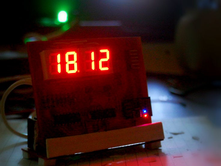
If you've thoroughly check everything and have faced no problems, congratulations, you have created a working clock! Be sure to switch on your wifi network, otherwise the clock will show the time as 00:00.
As you can see in the 1st picture above, the clock shows the time OK, but it isn't that easy to read, especially from a distance (depends on the quality of your 7seg displays). TO fix this problem, I used tracing paper to cover the displays. The result is, much much better contrast. Refer to the pictures above.
Step 10: The Base/Power Supply...
I will be powering my clock from my benchtop 12V power supply, so to bring the voltage down to 3.3V I used an LM317 regulator, using the resistor values shown in the above diagram (use this calculator for resistor values for the lm317).
For aesthetics I added an ice-cream stick covered in white tape on the front like this (its glued on to the 3 pin header):
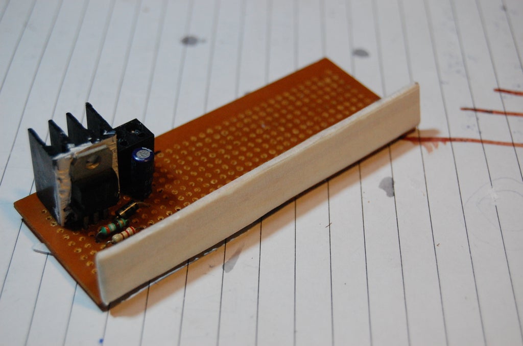
The LM317 power supply board, apart from bringing down the voltage, also acts as a stand for the clock:

For stability I added 4 pieces of rubber on the base PCB:


Step 11: Power It Up!
After troubleshooting and checking all circuits, its time to power the entire circuit! Simply insert the clock board to the power supply board, paying attention to correct polarity.
Voila, a working clock!
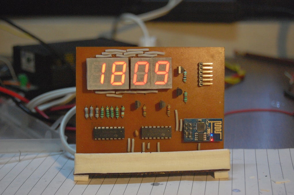

If you desire to have your clock battery powered, use 3 AA cells, through a low voltage dropout 3.3V regulator like the AMS1117. Or instead you can use a lithium-ion battery as a backup cell.


