Introduction: ESP8266 ESP-12E UART Wireless WIFI Shield TTL Converter Uncomplicated
This guide is intended to help people who have purchased the ESP8266 ESP-12E UART Wireless WIFI Shield TTL Converter and do not know how to use it with Arduino.
Initially, this tutorial was written in Portuguese here in Brazil. I tried my best to write it in English. So forgive me for some mistakes that might be in writing.
This instructables was divided as follows:
Step 1: Getting to Know the ESP8266 ESP-12E UART Wireless WIFI Shield TTL Converter for Arduino
Step 2: Firmware Upgrade on ESP8266 ESP-12E UART Wireless WIFI Shield TTL Converter for Arduino
Step 3: Shiald, Shield, More and Moer? Does It Matter?
Step 4: Shield Moer - Solving RX / TX Serial Communication
Step 5: Web server with ESP8266 ESP-12E UART Wireless WIFI Shield TTL Converter for Arduino
I recommend that you read all the steps to learn as much as possible about this shield.
Step 1: Getting to Know the ESP8266 ESP-12E UART Wireless WIFI Shield TTL Converter for Arduino
The ESP8266 ESP-12E UART Wireless WIFI Shield TTL Converter (Shield WiFi ESP8266) makes it easy to connect the Arduino to WiFi networks through the ESP8266. When using it, it is no longer necessary to mount a circuit with several components and wires to interconnect an ESP8266 to the Arduino, simply attach the board to the Arduino, position the DIP switch path according to the shield operating mode and program the Arduino to connect to WiFi networks. In addition, the board can be used without the Arduino, as it has all the pin-outs of the ESP-12E available.
In the shield there is the information that it was created by a person named WangTongze and who owns the rights of it is the elecshop.ml. Initially the shield's creator tried to raise funds for his project through Indiegogo (collective funding site), but he was unsuccessful in raising money.
Features of ESP8266 model ESP-12E:
- 32-bit RISC architecture
- Processor can operate at 80MHz / 160MHz
- 32MB flash memory
- 64kB for instructions
- 96kB for data
- Standard native WiFi 802.11b / g / n
- Operates in AP, Station or AP + Station mode
- It has 11 digital pins
- It has 1 analog pin with 10-bit resolution
- Digital pins except the D0 have interrupt, PWM, I2C and one wire
- Programmable through USB or WiFi (OTA)
- Compatible with Arduino IDE
- Compatible with modules and sensors used in Arduino
Below you can read the main features of this shield:
- Size of the Arduino Uno R3 and the pinning is compatible with Arduino Uno, Mega 2560, Leonardo and derivatives.
- Minor versions of the Arduino (Nano and Pro Mini, for example) are compatible, but connections must be made through jumpers.
- Arduino voltage (5V) is used to power the shield.
- Has AMS1117 3.3V voltage regulator, so the 5V voltage supplied by the Arduino is reduced to power the shield without the need for external power.
- It has built-in logic level converter, so the Arduino TTL level (5V) does not damage the ESP8266 that operates with TTL 3.3V level.
- It has a 4-way DIP switch that serves to change the operating modes of the board.- Available operating modes: WiFi Shield for Arduino / sending AT commands through Arduino / firmware upgrade through USB Serial external / standalone converter.
- It has indicative LEDs (PWR / DFU / AP / STA).
- Because it is in shield format, it allows other shields and modules to be inserted.
- It has the ESP-RST button to reset the ESP8266.
- The ESP8266 ADC pin is available in two forms on the board, the first on a pin with 0 to 1V reading range and the second form in the 0 to 3.3V range.
In the image the main parts of the shield are highlighted:
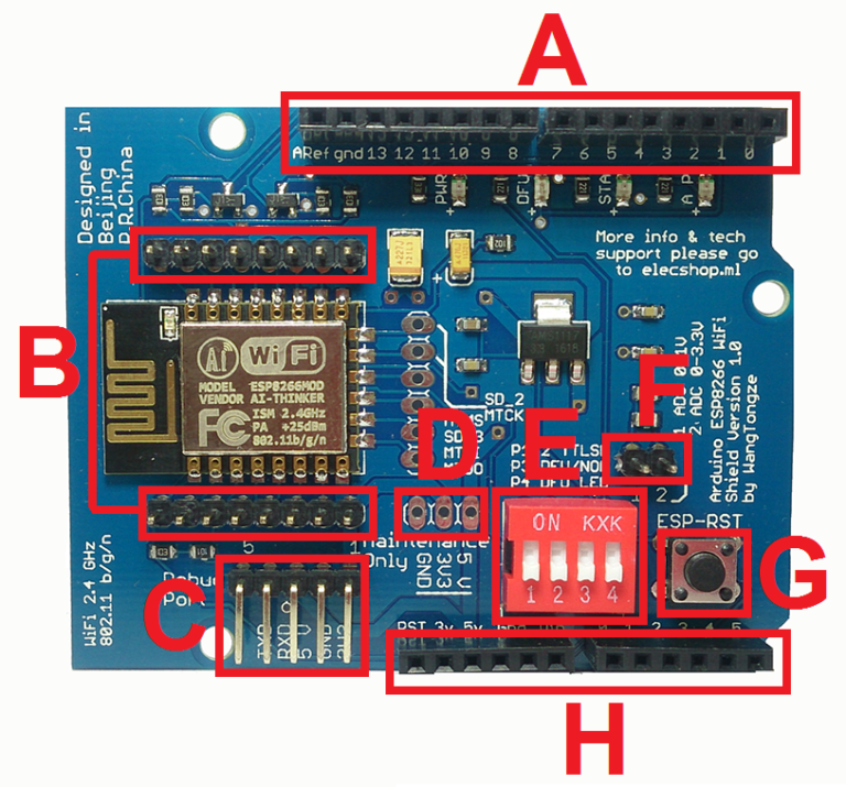
A (DIGITAL PINS): sequence of pins used by the Arduino.
B (ESP8266 PINS): ESP8266-12E and their respective pins. On the back of the plate there is the nomenclature of the pins.
C (EXTERNAL SERIAL USB ADAPTER CONNECTION): Pin sequence used to connect the external Serial USB adapter for firmware update or debugging of the ESP8266.
D (SHIELD MAINTENANCE PINS): A three-pin sequence identified as Maintenance Only and used to verify that the voltage regulator is receiving and supplying the voltages correctly. IT SHOULD NOT BE USED AS A SUPPLY SOURCE.
E (DIP SWITCH TO MODIFY OPERATING MODES): Four-way DIP switch to change operating modes.
CONTACT 1 (P1) and CONTACT 2 (P2): used to connect the RX (represented by P1) and TX (represented by P2) of the ESP8266 to the Arduino D0 (RX) and D1 (TX) pins. P1 and P2 in OFF position disable the RX connection from ESP8266 to Arduino TX and TX from ESP8266 to Arduino RX.
CONTACT 3 (P3) and CONTACT 4 (P4): used to enable and disable the firmware upgrade mode for ESP8266. To enable firmware write / load on ESP8266, P3 and P4 must be in the ON position. When P4 is in the ON position, the DFU LED will light, indicating that the ESP8266 is enabled to receive the firmware. To disable the firmware update mode and set the ESP8266 to normal operation, simply set P3 and P4 to OFF.
NOTE: All 4 contacts in the OFF position indicate that the ESP8266 is operating in normal mode next to the Arduino.
F (AD8 FROM ESP8266): pin assignment for the ESP8266 ADC. A pin operating in the range of 0 to 1V and another pin operating in the range of 0 to 3.3V. These pins will only be used when using ESP8266 alone (standalone mode).
G (ESP8266 RESET): button used to reset ESP8266. Whenever you change the position of the DIP switches, you must press the ESP-RST button.
H (ANALOG PIN AND POWER SUPPLY): sequence of pins used by the Arduino.
This shield has a peculiarity in the contacts P1 and P2 of the DIP Switch and this particularity, in fact it generates a great doubt in the people who try to use the shield.
According to the shield's creator, when connecting it to the Arduino only 2 pins will be required. These pins would be D0 and D1 (Arduino's RX and TX respectively) and in addition, the DIP Switch's P1 and P2 contacts on the shield must be in the ON position for the connection.
In one of the only Chinese documents I've gotten about this shield, the creator of the board says:
P1 and P2 are bit encoders and are used to determine whether or not the ESP8266 serial is connected to Arduino D0 and D1.
In another section of the document it is mentioned:
This expansion board keeps the Arduino serial busy, connecting RX from ESP8266 to TX from Arduino and TX from ESP8266 to Arduino RX.
The Arduino's D0 (RX) and D1 (TX) pins correspond to native serial / USB communication, so these pins stay busy whenever we send code to the board or use the serial monitor. Therefore, if the P1 and P2 contacts of the shield are in the ON position, the ESP8266 will be using Arduino D0 and D1 and it will not be possible to send codes or use the serial as it will be busy. In addition, to send AT commands to the shield, it is necessary that the ESP8266 RX is connected to the Arduino RX and that the ESP8266 TX is connected to the Arduino TX. This will only occur if we invert the connections as shown in the image below:
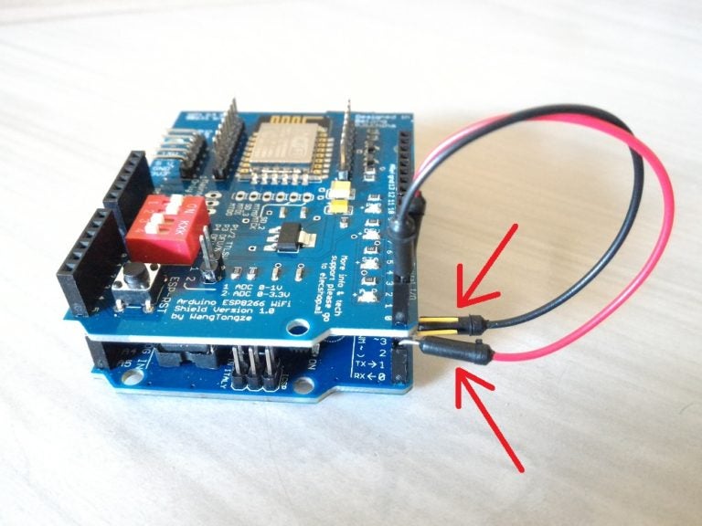
See I've bent the D0 and D1 contacts of the shield, and connected the Arduino D0 to the D1 of the shield and D1 of the Arduino to the D0 of the shield. When using the connection in this way (Arduino being used as a connection bridge), I was able to send AT commands to the ESP8266 and confirmed what I already imagined.
The shield's standard form of operation requires that a code (webserver or firmware, for example) be loaded into the shield and another code is loaded into the Arduino to send, receive, and interpret the data coming through the native serial. More details on this form of communication will be seen in the next steps.
Anyway, this feature of the shield does not interfere in its operation, since we usually emulate a serial on other Arduino digital pins so that we can have the native serial available. In addition, if it is necessary to send AT commands to the shield, we can connect it to the Arduino through four cables or use a serial USB converter.
Finally, the shield was very stable and made the assembly of circuits very easy. I tested with Arduino Uno R3 and Mega 2560 R3.
In the next step you will learn how to upgrade / change the shield firmware.
Step 2: Firmware Upgrade on ESP8266 ESP-12E UART Wireless WIFI Shield TTL Converter for Arduino
To connect the shield to the computer it is necessary to use a serial USB converter. If you do not have a conventional serial USB converter, you can use the Arduino Uno R3 converter as an intermediate. There are several models of serial USB converters on the market, but for this tutorial I used the PL2303HX TTL Serial USB Converter Adapter.
To upgrade the shield, use the:
The firmware that will be used is:
Ai-Thinker_ESP8266_DOUT_32Mbit_v1.5.4.1-a AT Firmware
Once you have downloaded the program and firmware, copy both to the root (drive C) of your Windows.
Unzip flash_download_tools_v2.4_150924.rar and the FLASH_DOWNLOAD_TOOLS_v2.4_150924 folder will be generated.
- Using the Arduino Uno R3 serial USB converter as an intermediate:
The next step is to connect the shield to the computer. If you do not have a standard serial usb converter, you can use the Arduino Uno R3 to bridge the shield and the computer. In addition to the Arduino Uno R3 with USB Cable you will need:
01 - ESP8266 ESP-12E UART Wireless WIFI Shield TTL Converter
04 - Male-Female Jumper Cables
NOTE: Before mounting the Arduino wiring diagram, you must load a blank code on the board to ensure that the serial USB converter is not being used. Load the code below into your Arduino and proceed:
void setup() {
  // put your setup code here, to run once:
}
void loop() {
  // put your main code here, to run repeatedly:
}
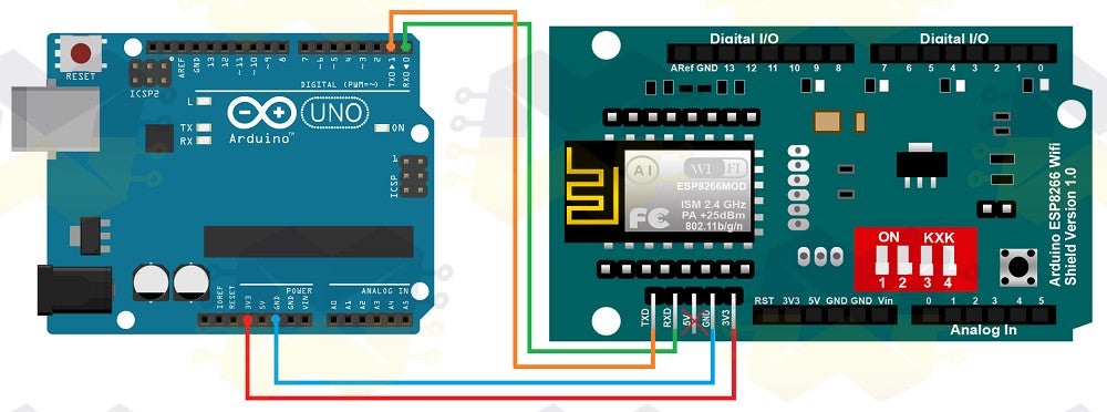
NOTE: Be aware when attaching the 3.3V shield pin to the Arduino.
- Using the Serial TTL USB Converter Adapter PL2303HX:
You will need the following items in addition to the PL2303HX TTL Serial USB Converter Adapter:
01 - ESP8266 ESP-12E UART Wireless WIFI Shield TTL Converter
04 - Male-Female Jumper Cables
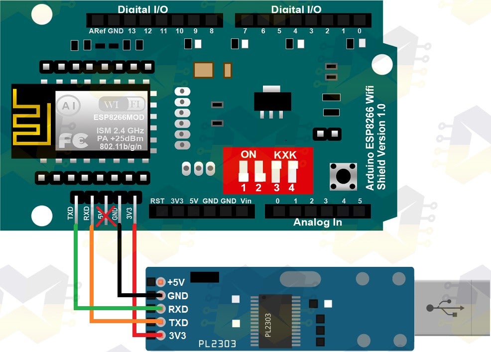
NOTE: The PL2303 has 5V and 3V3 power. Use 3V3 power and ignore the 5V pin.
After you make one of the above connection schemes, simply connect the USB cable (to the Arduino and the computer) or the serial USB converter to the computer.
Then go to the 'Control Panel' in Windows, 'Device Manager', and in the window that opens go to 'Ports (COM and LPT)'. You can see the connected device and the COM port number on which it was allocated. As a demonstration, I connected both the Arduino and the serial USB converter on the computer and in the image below you can see how the devices appear in the manager:

If you are using PL2303HX and it is not being recognized by Windows, access the post Serial TTL USB Converter PL2303HX - Installation in Windows 10, see how to solve it and then return to continue.
Now go to the FLASH_DOWNLOAD_TOOLS_v2.4_150924 folder and run ESP_DOWNLOAD_TOOL_V2.4.exe:
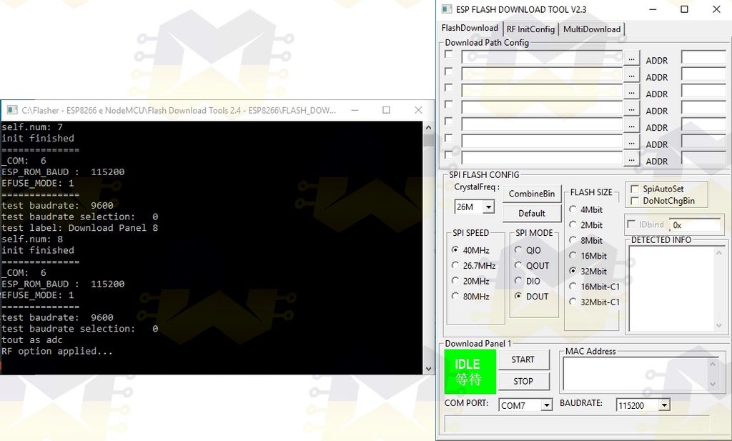
On the shield, place the P3 and P4 contacts of the DIP Switch in the ON position and then press the ESP-RST button on the card so that the shield enters firmware upgrade mode:

With the program open, uncheck the 'SpiAutoSet' option, select the COM port, select the 'BAUDRATE' 115200, uncheck any checkbox marked in 'Download Path Config', configure the other options as shown below and click 'START':

If communication with ESP8266 WiFi Shield is OK, you will see information in 'DETECTED INFO', 'MAC Address' and 'SYNC':

NOTE: If the program returns 'FAIL', check if you have selected the correct COM port, check if the P3 and P4 keys of the DIP switch are ON, click the ESP-RST button, click STOP and again click START.
In 'Download Path Config' you should select the file 'Ai-Thinker_ESP8266_DOUT_32Mbit_v1.5.4.1-a AT Firmware.bin' downloaded. Click on the '...' of the first field and in the window that opens navigate to the folder where you placed the firmware and select the file 'Ai-Thinker_ESP8266_DOUT_32Mbit_v1.5.4.1-a AT Firmware.bin'. In the 'ADDR' field fill in the offset 0x00000 and check the checkbox to finish. When finished, you will have the settings as shown below:

Now click START to start the process:
NOTE: If you are using the Arduino serial USB converter as an intermediate between the shield and the computer, click on the shield's ESP-RST button before clicking START. If you are using a conventional serial USB converter this procedure is not necessary.

Wait for the firmware upgrade process to complete (it will take approximately seven minutes for the process to complete):

After completing the firmware upgrade process, close the ESP_DOWNLOAD_TOOL_V2.4 windows, return the P3 and P4 contacts of the DIP Switch to the OFF position and press the ESP-RST button on the shield so that it can exit the firmware upgrade mode.
Now open the Arduino IDE so you can send AT commands to the board to verify that the firmware has been updated correctly and that the board is responding to the commands.
With the IDE open go to the 'Tools' menu and then in the 'Port' option select the COM port. Note in the image below that I selected the COM7 port (your port will probably be different):
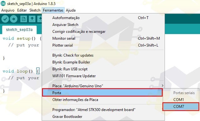
You do NOT need to select the board in the IDE as this is irrelevant to sending AT commands.
Open the 'Serial Monitor' and in the footer check if the speed is set to 115200 and if 'Both, NL and CR' is selected:

Now type the command 'AT' (without quotes) and give 'ENTER' or click 'Send'. If the connection is working you will have to return the 'OK' message:

NOTE: If sending the command DOES NOT receive any feedback or receives a random character string, change the speed from 115200 of the serial monitor to 9600 and send the command again.
In the 'Serial Monitor' type the command 'AT + GMR' (without quotes) and give 'ENTER' or click 'Send'. If you receive feedback as shown below, then your ESP8266 WiFi Shield has been updated successfully:

If you want to change the communication baudrate with the 9600 shield, enter the command 'AT + UART_DEF = 9600,8,1,0,0' (without quotation) and give 'ENTER' or click 'Send'. If you receive the information as shown below, then the communication speed has changed:
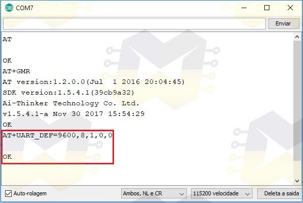
NOTE: When changing the shield baudrate, you should also change the speed from 115200 to 9600 in the Monitor Serial footer. Then send the 'AT' command again (without quotation marks) and press 'ENTER' or click 'Send'. If you receive the 'OK' as a return then the communication is working.
If you want to use the shield to assign WiFi to the Arduino, the ideal communication speed is 9600 baud.
In the next step you will find out what shield you have, since it is possible to find at least three shields on the market that seem to be the same, but in fact these boards have some points that differ them, even in the question of working with the Arduino through communication through the native serial.
Step 3: Shiald, Shield, More and Moer? Does It Matter?
If it is the ESP8266 ESP-12E UART Wireless WIFI Shield TTL Converter, it is possible to find at least three boards that are apparently the same, but in fact these boards have some points that differ them, even in the question of working with the Arduino through native serial communication.
Following you can see what differentiates the boards and find out which one is yours.
Shiald WiFi ESP8266:

Note that on this board the word Shield is written "Shiald" and the word "more" has the "m" in lower case. In the tests I did for a long time, the board did NOT show any flaws in its functioning.
Shield WiFi ESP8266:
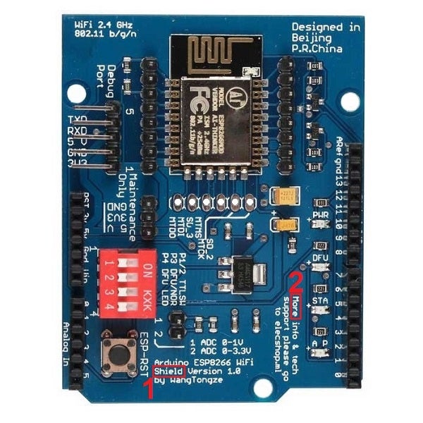
Note that on this board the word Shield is written correctly and the word "More" has the "M" in uppercase. In the matter of operation, this board behaves in the same way as the Shiald version, that is, the board is not faulty.
So you mean that the Shiald and Shield boards only have differences in the issue of PCB silk?
Yes, these two cards only have difference in the matter of the writing of two words. The circuit on both boards is the same and both work perfectly with the Arduino or alone (standalone mode). Considering that the Arduino has the correct code loaded and that one of the shields is also with the correct firmware, after attaching the shield to the Arduino and connecting the USB cable, simply put the P1 and P2 contacts of the DIP switch in the ON position and the communication through native serial (pins D0 and D1) between the boards will be made.
Some say that this Shiald version has the unstable wireless connection, but I assert that there is no instability at all.
Shield WiFi ESP8266 (Moer):

Note that on this board the word Shield is written correctly and the word "More" is written "Moer", that is, wrong. Unfortunately this board does not work the way it should and if it is attached to the Arduino (with the DIP switch contacts OFF or ON) and the user tries to load a code on the Arduino, an error message will appear in the IDE as the loading will fail.
If your shield is the one that comes written in Moer and you have had trouble using it with your Arduino through native serial communication, go to the next step and learn how to solve the problem. If your shield IS NOT THE Moer, skip to Step 5.
Step 4: Shield Moer - Solving RX / TX Serial Communication
If this board (Moer) is coupled to the Arduino (with the DIP switch contacts OFF or ON) and the user tries to load a code on the Arduino, an error message will appear in the IDE as the load will fail. This is due to a component error used in shield construction.
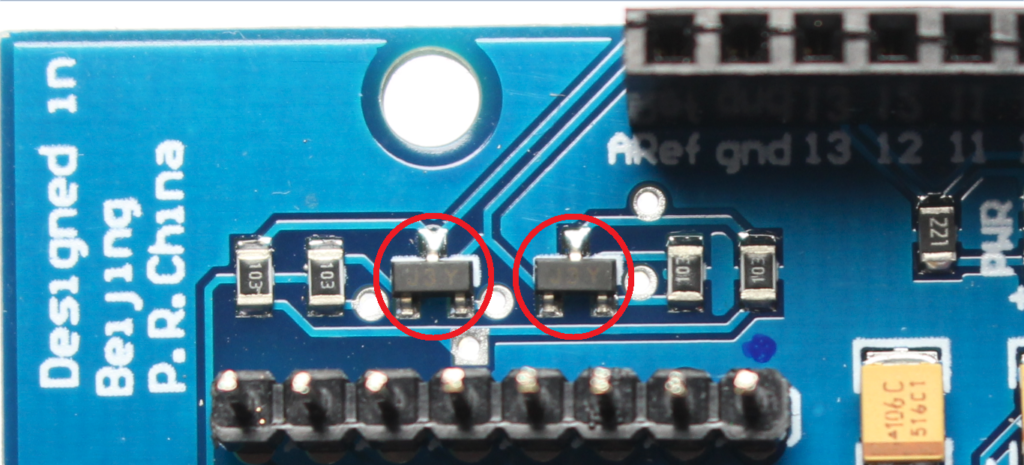
The shield that has correct construction and operation, has welded two Channel N MOSFETs and are identified as J1Y. One of the J1Y transistors is connected to the ESP8266 RX and the other is connected to the ESP8266 TX. In the image below you can see the two transistors highlighted:

This J1Y transistor is a BSS138 whose purpose is to enable 5V logic level circuits to communicate with 3.3V logic level circuits and vice versa. Since the ESP8266 has a logic level of 3.3V and the Arduino has a logical level of 5V, it is necessary to use a logic level converter to ensure the perfect operation of the ESP8266.
In the shield Moer, there are soldered on the board two transistors identified as J3Y. In the image below you can see the two transistors highlighted:
The J3Y transistor is an S8050 NPN and this type of transistor is commonly used in amplifier circuits. For some reason at the time of the construction of the shield Moer, they used the transistor J3Y instead of the converter of logic level J1Y.
In this way, the ESP8266's RX and TX pins will not work as they should and therefore the shield will not have any serial communication with the Arduino. As the shield communicates with the Arduino through the native serial (pins D0 and D1), with it coupled to the Arduino code loading (in the Arduino) will never be completed successfully, because in some cases there will always be approximately 2.8V in the RX and Arduino TX or constant 0V, all because of the wrong transistors.
After all this information, it is clear that the only solution for the shield Moer, is the replacement of J3Y transistors by J1Y transistors. For this procedure you will need in addition to the Moer shield of patience, and:
01 - Soldering Iron
01 - Tin
01 - Forceps or Needle Pliers
01 - Welding Sucker
02 - BSS138 (J1Y)
The BSS138 (J1Y) transistor is used in the 3.3V / 5V Logic Level Converter.
NOTE: The following procedure requires that you know how to handle a soldering iron and that you have the least welding experience. The components that will be removed and those that will be replaced are SMD components and require greater care and patience when welding with a common soldering iron. Be careful not to leave the soldering iron too long at the transistor terminals as this may damage them.
With the hot soldering iron, heat one of the transistor terminals and put some tin. Perform this procedure for each of the terminals of the two transistors. Excess welding at the terminals will make it easier to remove the transistors:

Now take the tweezers / pliers, hold the transistor by the sides, heat the side of the transistor that has only one terminal and force the transistor up so that the terminal comes loose from the solder. Still with the tweezers / pliers holding the transistor, try placing the tip of the soldering iron against the other two terminals and force the transistor up to finish releasing it from the board. Do this for both transistors and be very careful:
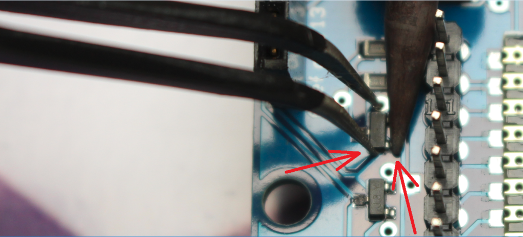
Removed the two J3Y ICs from the shield, simply position the J1Y IC in place, hold it with the tweezers / pliers, and heat each end of the shield so that the tin joins the contact. If the contacts are low solder, heat each one and place more tin. Do this for both transistors and be very careful:
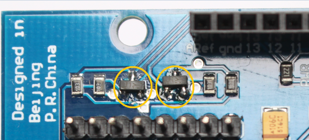
After the repair, its shield that previously had no direct communication with the Arduino, started to have connection to the board through the native serial (pins D0 and D1).
A first test to confirm that the repair was successful is to attach the shield (with all DIP switch contacts OFF) to the Arduino, connect the USB cable to the board and the computer, and attempt to load a code into the Arduino. If everything is OK, the code will load successfully.
Step 5: Web Server With ESP8266 ESP-12E UART Wireless WIFI Shield TTL Converter for Arduino
As a primary requirement to continue this step, you should have performed step 2.
As I mentioned earlier, in order to use the shield with the Arduino through the native serial (pins D0 and D1), it is necessary that a code be loaded into the shield and that Arduino be loaded another code to send, receive and interpret the data trafficked through the native serial. In the shield, we can put a firmware of AT commands and program the Arduino to send the commands to the shield in order to connect to a WiFi network and to control the inputs and outputs of the Arduino.
In this step we will use the WiFiESP library, since it already has all the necessary functions to integrate the ESP8266 (Shield WiFi ESP8266 in our case) to the Arduino and assign WiFi to the board. The WiFiESP library works by sending AT commands, then the wireless network connection of the router and any request made to the web server will result in the sending of AT commands to the shield.
For the WiFiESP library to work, the AT command firmware version must be at least 0.25 or higher. So if you do not know the AT command version of your shield, go to step 2 to update the board with firmware that has an AT command version of 1.2.0.0 and then return to continue.
One thing I identified during my tests with the shield and the Arduino is that because the communication between them occurs through the native serial (pins D0 and D1), it becomes necessary that the serial be of exclusive use for the communication between them . Therefore, I do not recommend using "Serial.print() / Serial.println()" to print information on the Arduino IDE serial monitor or any other program that displays serial information.
By default, the WiFiESP library is configured to display serial errors, warnings, and other communication information between the Arduino and ESP8266. As I mentioned before, the serial should be released for communication between the Arduino and the shield. Therefore, I edited a file from the library and disabled the display of all information in the serial. The only information that will be displayed on the serial monitor is the AT commands that the library sends to the shield to connect to the wireless network or the AT commands to execute requests made to the webserver.
Download the modified WiFIESP library and install it in the Arduino IDE:
In the library installation folder, simply access the path "WiFiEsp-master\src\utility" and inside it there is the file "debug.h" that was edited to disable the display of information on the serial. Opening the file in Notepad ++, for example, we have lines 25, 26, 27, 28, and 29 that show a corresponding numbering for the types of information that will be displayed on the serial monitor. Note that the number 0 disables the display of all information on the serial monitor. Finally, in line 32 I configured the "_ESPLOGLEVEL_" with value 0:

If you want to use the WiFiESP library in other projects with ESP8266 and need the information being displayed on the serial monitor, simply set the "_ESPLOGLEVEL_" to value 3 (default value of the library) and save the file.
Since your shield already has AT command firmware version 0.25 or higher, let's continue.
Attach the shield to your Arduino (Uno, Mega, Leonardo or other version that allows the shield to be attached), put all DIP switch contacts in the OFF position, connect an LED between pin 13 and GND, and connect the USB cable to the Arduino and the computer:

I used the Arduino Mega 2560, however, the end result will be the same if you are using another Arduino board that allows the shield to be coupled.
Download the code from the link and open it in the Arduino IDE:
If you are using Arduino Leonardo, go to lines 19 and 20 of the code, and change the word Serial to Serial1, as shown in the image below:

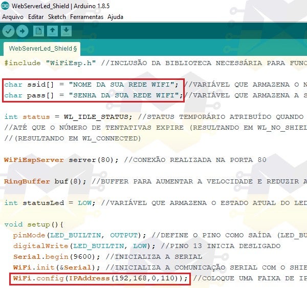
In the code you must enter the name of your WiFi network in the line char * ssid = "NAME OF YOUR WIFI NETWORK" ;, the password should enter in the line char * password = "PASSWORD OF YOUR WIFI NETWORK"; and on the WiFi.config line (IPAddress ... you should enter an available IP address on your wireless network as this code uses static IP:
In the "Tools" menu select "Board" and select the model of your Arduino. Still in the "Tools" menu, select the "Port" option and check the COM port in which your Arduino has been allocated.
Click the button to send the code to the Arduino and wait for loading.
After loading the code on the Arduino, disconnect the USB cable from the card, put the P1 and P2 contacts of the DIP Switch of the shield in the ON position and connect the USB cable to the Arduino again.
NOTE: As long as the shield's P1 and P2 contacts are in the ON position, you will not be able to send codes to the Arduino because the native serial will be busy. Remember every time you change the position of the switch DIP switches, press the ESP-RST button.
Immediately open the Arduino IDE serial monitor:

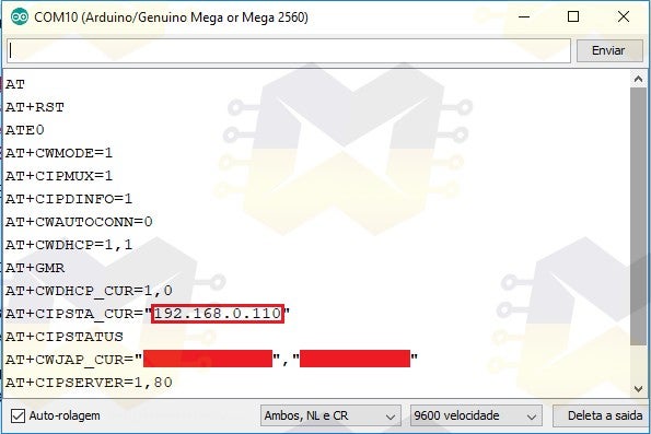
With the serial monitor open you can follow the AT commands that are being sent to the shield to run the webserver. If no information is displayed when opening the serial monitor, press the RESET button on your Arduino and wait.
Note that on the serial monitor the command "AT + CIPSTA_CUR" shows the IP address to connect to the webserver and the command "AT + CWJAP_CUR" shows the name and the password of the wireless network in which the shield is connected:
Copy the IP address shown on the serial monitor, open your internet browser, paste the IP address and press ENTER to access. A webpage similar to the one below will be loaded:
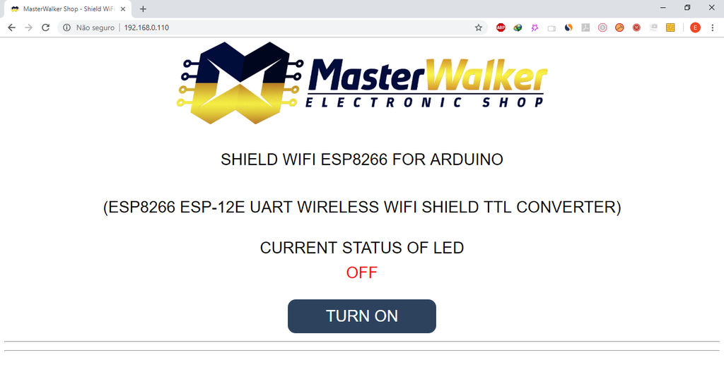
The web page has a button that will be responsible for turning on / off the LED connected to pin 13 of the Arduino. Press the button to turn on / off the LED and see that the current status is updated on the page.
You can also access the web page through a smartphone or tablet, for example.
See the video below for the final result:
This was a simple practice, because the purpose was to show how easy it is to use the shield with the Arduino. All the projects that you find on the internet that use the ESP8266 to assign WiFi to the Arduino, can be reproduced with this WiFi Shield, the difference is that you will not need to mount voltage dividers in the protoboard to communicate platforms, and in simple projects you will not have to worry about powering the circuit with external power supply. In addition, your project will have a much more pleasant aesthetic.
Now that you know how to integrate the Shield WiFi ESP8266 with the Arduino from a web server, simply modify the code and implement some more elaborate project or start developing your own code.
Once again, sorry for the failings in English.
If you have questions about the shield, just ask and I'll be happy to respond.


