Introduction: FSX Steam Edition + Arduino: Detecting Troublemakers


For years, I have been a fan of Microsoft Flight Simulator. I haven't played every version, but I did start with Flight Simulator 98. I later made a huge jump to Flight Simulator 2004 and shortly after found a disc for the first Combat Flight Simulator. Both were fun to play online before Microsoft made the decision to cut multiplayer from "zone.com". Later came the release of Microsoft Flight Simulator X which provided multiplayer support through the GameSpy network until they went out of business. It was nice of Steam to pick up the slack and provide the multiplayer capability to allow us to find new friends, but unfortunately there are bad people out there who make the friendly multiplayer world less than enjoyable sometimes...which creates the need for this project I am talking about in this Instructable.
Flight Simulator X was released with a few glitches that were never patched by Microsoft, nor Dovetail Games through Steam who later became the developers who took on the responsibility of patching and maintaining FSX. Although it was announced that the new version Microsoft Flight Simulator 2020 is soon to be released, I write this to share my knowledge to those playing FSX right now.
One bad glitch that gets heavily exploited is third party software (software that wasn't created for the malicious acts such as the ones I witness) that injects AI traffic aircraft into multiplayer sessions. This should not be possible, but it is. It was intended to have a tow plane visible to other players when using a sailplane, but FSX was never written with any parameters to make these tow planes disappear, or for a multiplayer host to remove them. So they just stay there until the multiplayer session ends. It wouldn't be so bad if it didn't cause negative system performance to everyone connected. Unfortunately, there are those sad types out there who abuse their ability to hide behind a monitor. I occasionally host FSX multiplayer sessions. Most of the time, honest people who actually want to play come in. Every now and then, someone comes in and damages my session with AI aircraft injections. Exposing their true identities to the world would be illegal, so instead I just created a tool I can use to quickly detect a malicious attacks then use process of elimination to find the culprit and block them from ever entering my multiplayer sessions ever again.
Step 1: Banning Troublemakers


The first time I had a troublemaker terrorize my session, he was using external software to inject a mass amount of random AI aircraft at a time into my multiplayer session. By process of elimination, I found out who it was and kicked him out of my session, but had to research further to find out how to ban this user from ever entering my session again. I had to do extensive research to find out how to add someone to that "Banned" list that appears in FSX when you are browsing multiplayer sessions because there are no clear instructions out there. I found out that you need to do it through the Steam client. It's easy.
On the top line of your Steam client, click [View] then [Players].
The next window will show 2 tabs: one that shows player in your current game (if you have it running), and the second shows a short history of who you were recently playing with. This is really handy to find the name of a culprit since Steam has no filter to prevent multiple users from using the same Steam ID.
When you find your culprit in the list, click the Profile link on the line with their name to open their Steam profile which will appear back on your main Steam client. From here you will find a couple of buttons to [Add Friend] or [More]. Click [More] and [ Block All Communication ] from that drop down menu. When you restart your FSX, that Steam user will be on your "Banned" list and can no longer enter your multiplayer session even if they change their Steam ID. Sadly, someone could get around this by creating a new Steam account and buying a new copy of FSX. The good news is: it would cost them money to do this. It's free for you to ban another account.
So after discovering this method, I started to discover that there are far too many of these troublemakers out there and I can't always catch them fast enough since it is literally by process of elimination to find out who is doing it. It would almost seem as if there are no other tools out there to help maintain a clean gaming environment in Microsoft Flight Simulator X, so I must create my own.
Step 2: About the Hardware and Software


HARDWARE - For this project, you will need to use the Arduino...particularly the Arduino Mega and I will explain why in the software section. There are many models of the Arduino, many places to purchase one online, and many knockoff models that are made and sold cheaper than the genuine original. I have money invested in the genuine, and a few knockoffs. Whatever kind you decide to buy... you will need the Arduino Mega. The required software is not compatible with any other Arduino chipset type except the ATMEGA2560. Another piece of hardware you will need is an 8 digit 7-segment module that uses the MAX7219 chipset. Optionally, you can add LED bulbs, breadboards, and a project box to hold it all together.
SOFTWARE - To get the Arduino talking to FSX, you will need 3 pieces of software. The first is FSUIPC which is installed into FSX as a module. It has a very wide range of uses (most of which I do not know or understand). This is an extremely well made piece of software by Pete Dowson and even though I use none of the features that come with a registered version, I bought myself a license as my way of thanking him for his work. This FSX add-on is needed to make number values within FSX accessible to software running outside of FSX. This is where MobiFlight Connector comes into play. Their software is completely free and they take donations through PayPal. This is the software that reads FSUIPC data, converts it as needed, and sends it to your Arduino Mega. MobiFlight Connector will not run unless Arduino IDE is installed
Step 3: Shopping List


You do not need to buy everything you see on this list, but at the very least, you will need an Arudino Mega, a MAX7219 8 character 7-segment display, and some jumper wires to connect the 2 together.
Parts list: I listed sources as best I can, but some parts I've found in local stores or on eBay where links routinely go bad and new ones created due to listings being created and expiring.
- - Arduino Mega:
- - Genuine: https://www.amazon.com/gp/product/B0046AMGW0/ref=...
- - Good knockoff: https://www.amazon.com/gp/product/B00D9NA4CY/ref=p...
- - Better knockoff: https://www.amazon.com/gp/product/B071ZGQMS6/ref=...
- - MAX7219 number display: https://www.amazon.com/gp/product/B01D0WSCJA/ref=...
- - Jumper wires: https://www.amazon.com/gp/product/B073M3PJVS/ref=p...
- - LEDs: https://www.amazon.com/gp/product/B07FKKN2TC/ref=...
- - Breadboard Set: https://www.amazon.com/gp/product/B01N3161JP/ref=...
- - Female Header Pins: https://www.amazon.com/gp/product/B07P5613GM/ref=.
- - 125mm x 83mm x 32mm Project enclosure box - found on Aliexpress
- - 6x1 sheet metal screws - found at Ace Hardware...project box did not have screws.
- - Resistors: On multiple sites...cheap on eBay and Aliexpress but LONG shipping times.
- - 75 Ω resistors
- - 620 Ω resistors
- - 33k Ω (33,000 Ω) resistors
- - Screws, nuts, washers, spacers:
- - 4-40 x 3/4 machine screws - found at Ace Hardware
- - Locking nuts to fit those machine screws - also found at Ace Hardware
- - Washers to fit those same machine screws - also at Ace Hardware
- - M3 6mm nylon spacers: https://www.aliexpress.com/item/32779698923.html?...
The Arduino Mega I listed as "Better knockoff" known as the Mega 2560 Pro along with the "Female Header Pins" is the Arduino Mega that I used for this project. It's smaller size allowed it to fit into the project box that I used.
Software list: Unlike the hardware that you might need all of, you will need ALL 3 of the programs listed here.
- - FSUIPC 4.974: http://home2.btconnect.com/petedowson/
- - Mobiflight Connector: https://www.mobiflight.com/en/index.html
- - Arduino IDE: https://www.arduino.cc/
Read ahead before deciding if or how you want to follow this setup.
Step 4: Tools Needed
- - Soldering Iron - I prefer it over a soldering gun
- - Rosin core solder
- - Utility knife
- - Dremel with cutting wheel
- - Dremel 561 Multipurpose Cutting Bit
- - Drill - you could use a hand drill, but a drill press is more controlled.
- - Hot glue gun
- - 1/4 wrench
- - Phillips head screwdriver
- - Safety Glasses
Step 5: Hardware Setup


This is possibly the hardest part after acquiring the hardware because it requires soldering in small places.
The MAX7219 number displays you buy will most likely not have header pins attached. They come included with the modules, but you will need to solder them yourself. See the pictures attached to this step for better visual reference. Something to note: I have found many posts online, including this site, which show this module with the header pins on the same side of the board as the number display. Doing this, or using angled pins for any reason at all, is not feasible for any project where you want to mount the display to something. I mounted mine into a project box. You will need to solder 5 pins to the DIN (data in) edge of the display. Soldering 5 pins to the DOUT (data out) edge is optional for projects where you might need to daisy chain more than one display onto a single controller board. In the pictures attached to this step, you will see that a MAX7219 display I have sitting on top of my roll of solder has pins soldered on both ends. I did not use this one for this setup, only the picture. That one went into a different project and the one I used for this project ONLY has pins on the DIN edge of the display.
On the Mega 2560 Pro board, I used the female header pins I posted a link to above. Depending on who made it and where you bought it, it will come with male header pins, some have them already attached (but cost more). I did not attach either of the 2x3 cluster pins nor the ones on the side with the reset button. The 2x3 clusters would have prevented me from using a screw on the mounting hole and the pins on the side with the reset button simply were not used in this project. Since the display needs ground, voltage, and 3 data pins and the LED's would have only needed ground and 4 data pins, all that could be provided from that one edge of the Mega 2560 Pro opposite of the reset button.
Whatever header pins you decide to use will not make a difference either way you go. Before I found myself with the need for this project, I did not have as many jumper wires in my inventory. When I built this, I had a Mega 2560 Pro with the female header pins already soldered on and was using it for experimenting with a solderless breadboard. Instead of spending money for short male to male jumper wires, I used the female header pins and 20 AWG Bell Wire to connect Mega 2560 Pro pins to the breadboard. The Bell Wire was available at my local Home Depot and I could cut it to any length I wanted, so why not, right?
That said, your choice of which header pins to install onto the Mega 2560 Pro will determine what kind of jumper wires you will need to buy. My setup required female to male jumper wires. If you solder the included male header pins, you will need female to female jumper wires. If you somehow decided on buying 5 pin female header pins to install onto your MAX7219 display, then you would need male to male jumper wires, or 20 AWG Bell Wire as an alternative.
You could stop before reading this paragraph and still have a working setup, or add in some LED bulbs. These will start to light up one by one as a certain number of aircraft start appearing somewhere (either in the sky or on the ground) during a multiplayer session. I used a 4cm x 6cm breadboard for this. The diagram picture above is what it looked like after I drew it out in a program called PCB Droid. I needed to draw it out first to figure out how to place the bulbs, resistors, and male header pins. I used 4 LEDs on this board: green, yellow, red, and a blinding bright blue that I bought from RadioShack a long time ago and never used until now. RadioShack has been out of business for a while now and I am unable to find that one online, but a white LED with a low Ω resistor will suffice. I used a high Ω resistor on green and yellow because have gotten enough players in my multiplayer sessions (who just want to honestly play) many times in the past that triggered those LEDs to light up. I don't want to be blinded with a possible "false positive" as I am trying to enjoy my Flight Sim time. I used low Ω resistors for the red and blinding blue because I want them to get my attention when that many aircraft are in my session. The pictures above show exactly what resistors I used for each LED.
This breadboard has 20 x 14 holes and of course I did not use them all. Unfortunately, the mounting holes on the board were too small for my screws, so I had to convert the 2x2 hole cluster in each of the four corners into better mounting holes by drilling them out. The squares in the corners of the diagram picture kind of give a description of how it looks. I would start with a 1/16 drill bit on my press since it was the smallest one I can find. After drilling in the middle of the 2x2 cluster, I would move up to a larger bit and drill again. When I had a hole big enough to fit the Demel cutting bit into it, I then shaped the new hole to fit my screws. I then placed the LEDs, resistors, modified male header, then soldered them into place to make it look as close to the diagram as possible. The slider switch on the one side of the board is an optional resistor bypass switch for my blinding blue LED. I wasn't sure about my resistor choice at first, so I installed this switch instead of removing it. I find myself keeping the switch off to force power through the resistor. After everything is soldered and I confirm that it all works, I usually cap my soldering with hot glue.
Before I forget to mention, the panel mount USB I used required me to chisel away some of the plastic around the micro USB end that connects to the Mega 2560 Pro. I realized AFTER drilling the mounting holes that the plug would not connect if it still had a strain relief attached. If you do this, cut the plastic off very carefully and only tiny fragments at a time so you don't accidentally cut any of the 4 wires inside of it. Yes, there is a sharp kink in the cable after it is mounted, but I plan to bolt this together and never take it apart again, so I don't have to worry about the wires breaking from the slack in the cable moving around.
Step 6: Hardware Assembly


So you could go one of two ways with this. You could connect all your hardware together and keep it all exposed (yes, it will function this way) or take it a step further like I did and mount it into a project enclosure box. Using an enclosure box is more difficult, but makes the hard work worth it.
First, you will need to cut a rectangle shape that will allow the face of your MAX7219 number display to show through the front. This is where you will need to use a Dremel with a cutoff wheel. I did this by laying the display face down on the box and using a pencil to draw the rectangle where I wanted it...in this case, the top and also as far left as I could get while leaving space for its mounting screw holes (I will explain why later). If you don't typically wear safety glasses while doing work like this, now is the time to begin. After making a mess with the Dremel to cut a rectangle shape into the box, I pushed the number display part of the module all the way through the newly cut hole so the board would lay flat and I could use a pencil to mark where to drill the mounting holes.
The LED breadboard I custom created is mounted below the number display when viewed on the front. This was a little harder to mark the hole placement since I did not print out the breadboard sketch, but I was able to make it work anyways. This required 4 holes for the mounting screws and 4 for the LED bulbs to protrude though.
I attached the Mega 2560 Pro to the back half of the enclosure box. This only had 2 mounting holes and was pretty easy to mark out before drilling. Using mounting screws would have been far more difficult if I had soldered the 2x6 male header pins that came included with the board. Because I mounted the display and breadboard to the left side of the box, there was enough space remaining on the right side to mount the Mega 2560 Pro and connect jumper wires to everything. Yes, it's a small box, but the reason I used this one is because I already had a few of this size in my stock for other projects which is why I used it here.
After all the cutting and drilling, I then mounted everything. The MAX7219 display and new LED breadboard each takes 4 screws, washers, nylon spacers, and locking nuts. After running each screw through a washer, then into the box from the outside, place a nylon spacer onto each one, then place the boards before attaching the locking nut. If those boards get a little scratched around where you tighten the nut, it will not break it. The Mega 2560 Pro will need to be mounted differently: screw through the washer, then into the box from the outside, then through the Mega 2560 Pro, then nylon spacer before attaching the locking nut. The idea here is to keep the nut away from the board because it would be too close to sensitive circuits otherwise.
The VCC pin on the MAX7219 needs to be connected to the 5V out on the Arduino. The GND pin on both the MAX7219 and optional LED board will need to connect to any ground pin on the Arduino. The DIN, CS, and CLK on the MAX7219 and positive voltage pins on the optional LED board can be connected to ANY of the digital numbered pins on the Arduino, regardless of which model you use. You will just need to take note of which module pins connect to which pin on the Arduino Mega or Mega 2560 Pro.
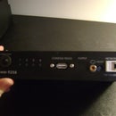
So now that everything is bolted down and connected, it is especially important to be able to connect this to a PC. The easy route would be to drill a hole in the side, run a micro USB cable into it, and tie a knot to keep it from getting jerked out. I used a panel mount USB. The Mega 2560 Pro connects using a micro USB and that is one option I could have gone. I could have used one that could connect a micro USB on the outside to a micro USB on the inside. I already had a panel mount USB cable in my stock that connected a full sized USB-B on the outside to a micro USB on the inside. It was just personal preference because there's no denying that full sized USB-B is much more durable than micro USB. Why not, right? All I had to do was find a spot on the edge where I knew it would fit, use my utility knife to cut a part of it out, mark and drill holes to attach it, then close up.
My project box did not come with screws to close it. I had to spend some time at Home Depot to find that I needed sheet metal screws.
Step 7: Software Setup


If you are comfortable with your soldering and connections, it's time to make it work for your Flight Sim.
First install FSUIPC found at the link above in Step 3. Just make sure your FSX is not running, then follow the setup procedure as normal. This will also give the option to install WideFS. You do not need to install it. If FSUIPC is installed correctly, you will see a new menu item in your FSX while you are playing. You do not need to do anything in the FSUIPC menu in Flight Sim for this setup.
Before installing MobiFlight Connector, you will need to have Arduino IDE installed. This can be downloaded from the main Arduino web site that can be found by clicking the link above in Step 3. You do not need to run this program, but you should do so at least once to ensure that your PC can see your Arduino Mega and upload code to it. There are many tutorials out there on how to use the Arduino IDE, so I will not go into details about it here. For a device as unique as the Mega 2560 Pro (even though it's one of many Arduino Mega knockoffs) that I used in my setup, I still wanted to make sure it worked. I just used Arduino IDE to upload the basic "Blink" script to it so I knew it would work.
After you have Arduino IDE installed and confirm that your PC can see your Arduino Mega, you can download and install Mobiflight Connector from their site by following the link I provide in Step 3. BEFORE YOU RUN IT, make sure your Arduino Mega is connected to your PC and properly recognized and using the correct driver. When you run Mobiflight Connector for the first time, it will need the install path of Arudino IDE so you will need to point it to that path. Next, it will offer to upload the MobiFlight firmware to your Arduino Mega. After MobiFlight reports that the firmware has been updated successfully, you will need to open the settings to tell it which kinds of hardware are connected to your Arduino Mega and which pins they are connected.
Open up the "Extras" menu and click "Settings" and navigate to the "MobiFlight Modules" tab to show the Arduino list. If MobiFlight Connector did not update the firmware automatically upon first opening, you can do that here...and you will need to do it before you can tell it what modules you have connected to your Arduino. You will need to right-click the Arduino, select "add a device" and click 7-Segment. Click on the new item that appeared in the list on the left, and on the right you can configure details and connected pins. This is where you will need to refer to your notes on which pins on the MAX7219 connected to which pins on the Arduino. It is very important that you select the correct pin numbers here for DIN, CS, and CLK. You have the option to choose the display's intensity. After testing it with a power meter, I found that I get less power draw by sliding it all the way to the left to make it dim. Also, I think it looks better and is less straining on my eyes when I am playing FSX in the evening. You could repeat this little process to add in each of the LED bulbs, but I will talk about that in the next step due to the unique complexity of configuring them. After you have the pins selected, you will need to save your configuration and upload it to your Arduino (this is an extra step in addition to the MobiFlight firmware you uploaded earlier).
After receiving the notification that your Arduino was successfully updated, you will need to tell MobiFlight what FSUIPC offsets to capture from Flight Sim and where to output them. On the main MobiFlight window, "Double click to add a new line" and give it a unique title such as "Number of Traffic Aircraft" and then click the [ . . . ] on the right to open it's configurations.
On the "FSUIPC" tab, you have the option of using one of the preset FSUIPC offsets that come included with MobiFlight Connector. All of these are quite useful, but it does not with everything that it is capable of doing. So ignore the "Load preset" section for this project. On the "Base settings" section, you will need to manually type 0x025C in the "Offset" box. Equally important, and do not forget this one, set the "Size in Bytes" dropdown menu to 4. Now move over to the "Display" tab on the top. Select your connected Arduino on the first line and "Display Module" on the second. This will make the bottom section appear to make the following changes: Check "Use Left Padding" use the dropdown to change the "0" to "Space" and check the boxes ABOVE "6" "7" and "8" not below them. The boxes above make that number digit appear. The boxes below make the decimal point next to that digit appear. Click the [ Test ] box and you should see your display "123" on the last 3 digits on your MAX7219 display. If this works, you are good to go to click [ OK ]. If not, still click [ OK ] to save your configuration. Once back on the main MobiFlight Connector window, you should save everything at this point before you do anything else. Whether or not your test was successful on the ConfigWizard window, you should close MobiFlight Connector at this point.
FOR REFERENCE: YOUR ARDUINO NEEDS TO BE CONNECTED TO YOUR PC'S USB PORT BEFORE YOU RUN MOBIFLIGHT CONNECTOR. If you connect your Arduino after starting MobiFlight Connector, it will not work. You can safely start Flight Simulator X before or after MobiFlight Connector.
Restart MobiFlight Connector. It typically opens with the last saved configuration file automatically. From here, you could either go back to the "ConfigWizard" for that config, or you could jump straight into testing with FSX. Often times upon first clicking that [ Run ] button, you might see "The connection to FSUIPC has been lost." Just click [ OK ] and wait. That [ Run ] button might gray out for a moment, then reappear. When it reappears, [ Run ] it again. MobiFlight Connector does not seem to hold a stable connection to FSX if it is open but not actively running. However, when it is running, it will stay that way for hours...and I know that from experience.
When you are playing Flight Simulator, this will only give you the number of other aircraft NOT INCLUDING YOUR OWN. In single player mode, it gives a number for how many aircraft are within 30nm even though it only shows labels for aircraft within 10nm. In multiplayer, it will show a number of how many aircraft are in the session regardless of distance even though it only shows labels for aircraft within 30nm. This only shows other aircraft besides your own. It will not show players not in an aircraft, players who are in the tower, or players who are riding with someone else. This is a HUGE help in quickly seeing a rising number of aircraft appearing. I will occasionally compare the number I see to how many I count on the player list on the chat window. When I see this number is higher than the number of players, I know that someone is either repeatedly calling tow planes, or using something like Ultimate Traffic Live to inject AI traffic. Let's hope that the new Flight Simulator 2020 has the built in ability to stop this kind of nonsense from happening.
Step 8: Optional Configuration: LED Bulbs


If you decided to NOT add LED bulbs to your setup, you can ignore this entire step.
One day, I was hosting a multiplayer session when I realized much too late that I was being attacked by AI traffic injections again. My attention was entirely on FSX and talking with my friends on Teamspeak, not my number display. What I needed was something that could get my attention much sooner. There was no way I was going to attach any kind of buzzer or beeper, but I could if I wanted to. I decided instead to add some LED bulbs.
To start this configuration, you will need to return to the MobiFlight settings then the MobiFlight Modules tab to add LED bulbs. Looking at my attached pictures, you will see that my Arduino configuration looks a little different now. The ones you saw in the other pictures were some I took for this instructable. The pictures in this step show the configuration that I actually use today. Along with the module config for my MAX7219 7-Segment display, I have my LED bulbs which had to be set up as individual "devices." I have another connected Arduino Mega, but it is not part of this setup...it is just something else I built. You will need to right click your Arduino, select "Add device" and click [ LED / Output ]. As you add each of your LED bulbs, you will need to select the connected pin, then give each LED a good "Name" so that you will know which one you are working with later when configuring it. I simply named my bulbs for their colors. Of course, save the Arduino configuration to your hard drive, then upload the configuration to your Arduino Mega. Click [ OK ]
The 3 sub-steps below will need to be repeated for each LED bulb.
LED STEP ONE: On the main MobiFlight Connector window, "Double-click row to add new config..." and type something like "Traffic Aircraft > 10" then click the [ ... ] button on that line. As before, you will want to manually set the offset 0x025C with the "Size in Bytes" at "4". This time, you will want to check the box next to "Transform" to adjust the value that is sent to your Arduino. The "value" is portrayed as a single dollar sign. You will need to add the equation to divide by ten with spaces between each item. In this one, you will need to type (I will spell it out): DOLLAR SIGN, SPACE, FORWARD SLASH, SPACE, ONE, ZERO. With this particular setup, my green LED will not light up until 10 planes are in my session. LED bulbs light up when the value sent to the Arduino is anything except zero...including negative numbers. Also to note, number fragments (decimal numbers) are rounded DOWN to the lowest whole number....example: "1.9" would be rounded down to "1"
LED STEP TWO: Now we need it to turn off when the number of aircraft number gets to 20 (another config will make the yellow bulb turn on). Move over to the "Compare" tab. Check the box next to "Apply comparison to modify the current value" then drop down the menu to select the greater than symbol (>) and type "1" on that line. Then type "0" (zero) on the box next to "set it to" and leave the "else set it to" box blank. To bring you up to speed: since the algorithm divides the number of aircraft by 10, this will make the green LED light up in this state. The "Comparison" tab settings will make this LED turn OFF when the new value should be 2 or more and will instead change it to zero.
LED STEP THREE: Move to the display tab. Select your Arduino on the top drop down menu, then "Pin" on the second. The third drop down menu will contain all your LED bulbs you added earlier. This first setup needs to be the green LED. There is a "Brightness" slider that does nothing. This was the reason I used resistors and recommend you use them too. After selecting your LED, click the [ TEST ] button to confirm it works.
You will need to repeat those 3 steps for your other LED bulbs. The first tab will need to be adjusted differently...in my case, I used 20 (instead of 10) for my yellow LED, 50 for my red LED, and 100 for my bright blue LED. The second tab will be EXACTLY the same for all your LED bulbs except the last one where you won't change it at all. On the third tab for each bulb, you will obviously want to select a different bulb than the previous.
Step 9: Final Thoughts and Experience
When I first built this, I had started with the box which had ONLY the number display mounted and the Mega 2560 Pro sitting inside loose. I figured that it would be enough, until I had another AI traffic injection attack again one evening. I was distracted by conversation with friends on Teamspeak and just enjoying my Flight Sim time. One of my friends noticed a "flood" of planes at an airport near by before I noticed that the number of aircraft kept increasing even though I didn't have that many players connected. It was one of those days where I had a lot of people in my multiplayer session, so my "process of elimination" that I had been using was not going to work. Instead, my quick reaction was to screenshot the chat window to capture all the players connected, then restart the session.
For days I was mad about this attack that had slipped by me and was trying to find out how to prevent that from happening again. One of my Teamspeak friends suggested setting a password. Another suggested to just block everyone who's names I had from that screenshot capture. Those are technically effective ideas, but I am not evil. Punishing everyone for the misbehavior of a few is completely unethical. I prefer the common sense idea to punish only the guilty individuals. After considering buzzers and beepers (which I later rejected), I settled on LED bulbs attached to resistors and a breadboard to upgrade my device.
While planning this out and before constructing it, I was hosting another FSX multiplayer session and watching my number display much closer and had another AI injection attack. Like the last time, I captured a screenshot of my chat window to record who all were connected. This list was much smaller than the previous one. After taking some time to match the two lists, I narrowed it down to three Steam ID's that were in my session during both attacks. Now with an even smaller list to work with, I took it a step further and found that 2 of those names were friends with 3 of my friends. The third name had no friends. The proof couldn't be more clear. Another player from my sessions ("How to" listed in Step 1). Just in case I was wrong, I monitored the other 2 players when they came into my session and never had any problems with either one of them.
Eventually I completed my project. I've had many more AI injection attacks on my multiplayer sessions since then, and I have been successful in quickly responding to kick the culprit from my session and banning them. Unfortunately since it is impossible to remove the injected AI, I am still forced to restart my multiplayer sessions. I really hope that Microsoft fixes this problem before releasing the new version next year.
As you may have seen from the pictures from Step 1 of this instructable, I have already built up quite a long list of troublemakers I have banned from my multiplayer sessions in FSX. Something that I am unable to comprehend: "Why do people have to be this way?" As far as I'm concerned, whatever problem it is in their lives that makes them want to make others miserable, they can take it somewhere else.
Important note for those who host their own FSX: Steam multiplayer server: This project will not be of much help if you leave your session running 24/7 without monitoring it. If you are wishing to ban troublemakers as I have, you will need to keep an eye on the account you are hosting with.
Writing this article involved a couple of weeks of snapping pictures and multiple re-reads to make sure I didn't miss anything. During this time, I've had 2 attacks on my multiplayer sessions that I was able to quickly detect and respond to...plus it kept pushing me to get it completed so I could get it out there faster. I am giving this idea for free. I do not have any intentions of making any money from it. If you like it and find it useful, share it out with others.


