Introduction: Fountain of Light
We are a class of Stanford students who, driven by our desire to replace the drought-stricken fountains on campus, decided to create an electronic fountain with light, instead of water, as the main medium.
Attachments
Step 1: Materials
STRUCTURE:
- 2.5" OD x 2.25" ID x 6 foot long acrylic tubes X6
- 24 inch x 12 inch Illusion Film (color: Clear Silky Moire) X1
- 3" OD and 2.87" ID and 6 foot long low-carbon steel tubing X1
- 0.06" thick and 24" x 24"General Purpose Low-Carbon Steel Sheet X1
- 4' x 8' sheet of plywood X4
- 2" x 4" plank of wood X14
- 25' x 20" Galvanized Steel Flashing x1
- Rusteze black gloss latex fast dry paint X1 pint
- Packaging foam x1 roll
- optional: dark smooth 1" stones x50-100
ELECTRONICS:
- 4 meter 60 LED/meter digitally-addressable RGB LED strips with black backing X7
- Teensy 3.1 X1
- (Optional) Speakers
- (Optional) male to male audio splitter
- 14A 5V Power Supplies X3
- Infared Distance Sensors 100cm - 500cm X2 (optionally more)
- 18-24 gauge 2x2 matrix m/f Molex connectors and adequate m/f connector pins X17
- Lengths of 18-24 gauge wire in at least 3 colors for line, ground, and data
- Breadboard (or protoboard for more permanence) X1
- 3.3V to 5V level switcher chip (ex. 74HCT245)
- (optional) MSGEQ7 (8 pin music equalizing component) X1
- (optional) 100k Ohm resistors x2
- (optional) 100 pF capacitors x3
- (optional) 0.1uF capacitors x2
- (optional) 0.01uF capacitors x1
Step 2: Developing the Design
For the design of the tubes, we wanted to emulate the crashing of waves on a rock in the middle of the ocean, so we arranged the tubes in an abstract manner with all the tubes pointing inward at different angles and cut to different lengths, so it looked like water splashing up into the air.
Step 3: Building the Base
For the bottom of the structure, we made a compartmentalized base composed of 6 triangles to make the base more mobile.
Using the dimensions in the first four photos above, we cut all the pieces of wood to size and drilled them together using household screws. We also designated the top of each triangle piece as the side with the extra 2x4 support since the top would hold most of the weight of the tubes.
Once all 6 triangles were created, we arranged them together in a hexagon, so that there was a solid outside for the base but the inside was open to allow for wires and power supplies to be hidden inside.
Step 4: The Tubes
We decide on the tube lengths and angles by playing around in Tinkercad and Solidworks to see which arrangement looked best from all angles. In the end, we decided on the arrangement in the photo above with these lengths and angles: (this is up for you to decide on, but you should make sure the center of mass of all the tubes is towards the center of the structure)
Base Plate Color Length of Tube Angle from the Vertical
Red 6 ft 13 degrees
Orange 5 ft 30 degrees
Yellow 5 ft 8 in 26 degrees
Green 5 ft 40 degrees
Blue 4 ft 6 in 34 degrees
Pink 3 ft 34 degrees
Brown 3 ft 45 degrees
After trying the lights through various materials, we decided the light was best diffused and looked most fluid when it was in the acrylic tube and surrounded by the Illusion film.
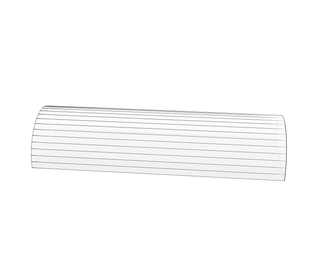
However, it was difficult to get the illusion film to perfectly cover the inside of the tube without overlap or gaps, so we cut the pieces of illusion film so that there was about an 1/8" overlap. Then we rolled each piece up and put it into its respective tube, taking care not to twist the film.
To attach each tube to the wood base, we first made base plates of 7" x 7" cut out of the steel sheet and then drilled a hole of 1" diameter in the middle of the base plate for the wires to pass through and drilled four smaller holes in the four corners, each large enough for a standard packaging screw. Then, we cut the steel tubing into smaller tubes at the desired angle (see above) and long enough so that the shortest side of each tube was 4". Then, we soldered the tubes to the base plates so that the tube is aligned with the large hole.
Before we put the tubes into the steel holders though, we lined the inside of the steel tubes with packaging foam to prevent the steel from scratching the tubes and to create a more secure fit.
Step 5: Coding
We began by becoming familiar with the FastLED library, which provides functions that allow an Arduino to interact with LED strips, and used the tools it provided to develop algorithms that made the LEDs turn on in patters reminiscent of water. Our program cycles through four main modes, each of which are affected by readings from two infrared distance sensors.
The original program architecture lagged when rendering all seven strips forcing us to overhaul our design. After some research, we found a library that was optimized for Teensy (a more powerful Arduino) and WS2811 (the model of LEDs we ordered). This library is called OctoWS2811 and can run up to 8 LED strips in real time. We used OctoWS2811 in combination with FastLED. This required a rewrite of our code to use one long array of pixels instead of a two-dimensional array.
You can program the Teensy easily with the same code you would use for Arduino by downloading an extension to the original Arduino environment called Teensyduino. Here's a link.
We added IR sensors to allow interaction with the fountain. In order to "smooth out" readings from the sensors, we used a library called RunningMedian.
Here is a link to our final code, if you want to use it directly or copy and modify it.
Step 6: The Board
Begin the process using a breadboard to test all your connections before you make them permanent. (Warning: when using power supplies, don't run much current through the breadboard itself. We used a hacked low current power supply to test our LED strips individually with the breadboard and the code before we finalized our project - see first picture). When you decide to finalize your board, solder everything to a protoboard.
We ran all 7 LED strips and 2 IR sensors from one Teensy to avoid synchronization issues. Included in this instructable is the Teensy pinout for your convenience. OctoWS2811 has some specifications for what you should use each Teensy pin for. We've linked to the page already, but you might want to check it out again here.
To make the LED strips work properly, you'll need to increase the Teensy's output voltage from 3.3V to the 5V that the LED strips need. We did this using level switcher circuits and 2 buffer chips that we had lying around. A 74HCT245 level shifter would be good to use. There are a variety of choices, but you need to make sure it can match the speed of the LED strips.
Connect the LED and IR sensor data wires to the correct pins on the Teensy, through the level shifter. Connect the Teensy to power and ground. This is the basic board you'll need.
If you want the music equalizer, you'll need the MSGEQ7 chip as well (pinout picture included) and a slightly more complicated circuit board, also shown two ways in pictures included above.
Step 7: Wiring It Up
In terms of wiring, we soldered a bunch of molex connector cables to everything to make it easy to assemble and disassemble. These are the things you need to connect:
- Protoboard to each LED strip (data)
- Each LED strip to a power supply (line, gnd --- power supplies should each support about 3 LED strips at full brightness)
- Protoboard to a power supply (line, gnd)
- Protobard to each IR sensor (data, line, gnd)
- (optional) speakers to power supply (line, gnd)
In this set up, the IR sensors receive power from the protoboard itself since they require so little power, whereas everything else is connected directly to a power supply. Make sure your wires are the appropriate size for the current running through them, and make sure everything is connected to the same ground. To do this you'll need to connect the three power supplies together, ground to ground.
Step 8: Miscellaneous
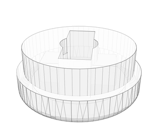
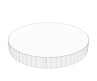
In order to hold up the led strings (since they are doubled over in the tubes) and to cover the top of the tubes, we designed and 3D printed caps for the tubes, as shown in the photos and files above. We used a makerbot printer to print the caps with these settings: structures and rafts on, infill at 13% and 2 shells. The outer diameter should be 2.5" and the inner diameter should be slightly less than 2.25". The cap's lid should be slightly less than 2" in order to snap into the rest of the cap. You may have to vary these settings slightly based on you 3D printer.
To make the base look more visually appealing, we painted the wooden base and the flat portion of the steel plates black.
To attach the steel tube holders to the base, we first aligned the tube holders on the base and outlined their location and each hole for wires. Then, we drilled through the base at each outlined hole, then attached the tube holders/steel plates to the base using standard packaging screws.
Then, we wrapped the galvanized steel flashing around the base and bent the flashing so that it was flush to the sides of the hexagon to make a raised edge around the outside of the hexagon. We secured the flashing to the base with the use of various adhesives, including magnets and Velcro- you are free to use whichever adhesive works best for you. Then, we took some smooth stones with about 1" length and covered the top of the base with them.
Step 9: Putting Everything Together
We attached the three power supplies and the protoboard to the base with velcro. We threaded the LED strips through the tubes and through the base of the steel holders. Wiring from there was easy because of the Molex connectors we added earlier. We numbered the sides of each connection to make it easy to set up quickly.
We connected each power supply to a power strip, and drilled a hole in the side of the base to thread the power strip cord. The entire light structure could then be turned on by plugging in one cord.
To finalize our project, we took some smooth stones with about 1" length and covered the top of the base with them. Then, we plugged in the cord and turned on our light fountain.


