Introduction: Fpga Controlled RC Servo Motor Robot Arm - Digilent Contest
FPGA controlled servo motor robot arm
The goal of this project is to create a programmable system that can perform soldering operations on perf board. The system is based on the Digilent Basys3 development board and it will be capable of soldering components on the test perf board in order to create small electronics projects with a limited number of components that have been mounted previously by the user.
Because my experience with fpga programming and Vivado software is limited, I used the servo motor command principle that I found here: https://www.instructables.com/id/Controlling-Serv... and built up from there until I was able to control my robot arm, so some of the files I use in my project were created by the engineer who uploaded the tutorial available in the previously mentioned link.
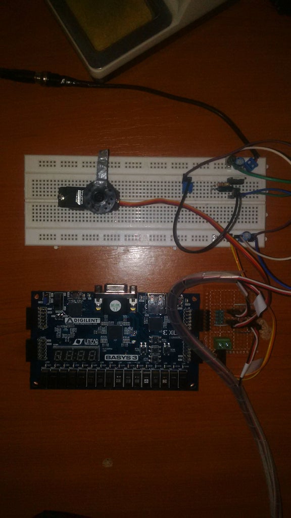
The project can control 4 servo motors. In order to do this I created a replica of the "Pmod CON3" using the schematic and documentation available on the Digilent website: http://store.digilentinc.com/pmod-con3-r-c-servo-connectors/.
This Instructable will help you understand how to control 4 servo rc type motors independently using a fpga board. Each motor can be moved at a 0, 45, 90 and 170 degrees position, since the servos of my robot arm can only move from 0 to 180 (or 170 in my case) degrees.
Because of some problem I encountered on one of my servo motors (probably poor quality), I set the Basys3 board to move the motors up to 170 degrees to avoid the destruction of the (already) faulty servo motor. Anyway, a 170 degrees limit seems enough for this project to work properly.
Step 1: Components and Equipment
- four servo rc motors (S05NF STD or S06NF STD) or a servo motor robotarm
- Digilent Basys 3 fpga board
- Xilinx Vivado software
- micro USB cable
- Pmod CON3: R/C Servo Connectors
- 5-7.2 volts DC supply
Step 2: Project Files
Extract the files and open the project using the Vivado software.
Attachments

Step 3: Connecting the Components
Connect each of the four servo motors into one of the four dedicated slot paying EXTRA attention to the configuration of the pins which is similar to the one on the original PmodCON3 (from left to right PWM, Vcc, GND).
Plug the DIY PmodCON3 into the upper side of the Basys3 Pmod Connector C. Attach the 5-8 Volts power supply to the DIY PmodCon3.
Connect the Basys3 board to the pc, open the project and generate the bitstream. Program the Basys3 using information on the Digilent website. https://reference.digilentinc.com/learn/programmable-logic/tutorials/basys-3-programming-guide/start
Use the push buttons and switches Sw0 and Sw1 on the Basys3 board to operate the servo motors.