Introduction: Getting Started With Arduino and ESP8266

ESP8266 can be used as an independent microcontroller with built-in Wi-Fi and two GPIO pins or could be used with another microcontroller through serial communication to give a Wi-Fi connectivity to the microcontroller. It could be used to make IoT sensors network to report sensor data to the internet or the internet connected dashboards, it could be used to make a home automation device that is connected to the internet or local network. ESP8266 could be used to develop an IoT based security system, smart plugs and lights, mesh networks or wearable devices. Because of its low cost, low power consumption and small size it could be used to develop any kind of IoT device.
Step 1: Shortly About Architecture and Features
ESP8266 Wi-Fi module has 32-bit RISC microprocessor clocked at 80Mhz and can be overclocked to 160Mhz. It has 32 KiB Instruction RAM, 32 KiB instruction cache RAM, 80 KiB user data RAM and all over that it has GPIO, 12C, ADC, SPI, and PWM
Step 2: Power Consumption
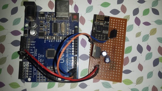
The maximum voltage and current required to operate ESP8266 Wi-Fi module is 3.6V and 120.5mA, the Arduino has 3.3V output pin but its output current is just 40mA that is not enough to run the esp8266, so voltage regulator LM317 is used to regulate Arduino’s 5V to 3.3V to make it run properly as LM317 maximum output current is 1.5A. ESP8266 I/O pins also run at 3.3V, so logic level shifter 3.3V zener diode is used to convert 5V logic coming from Arduino TX pin to 3.3V, but according to my experience there is not much need for it. It is all fine to simply make the circuit given in figure below
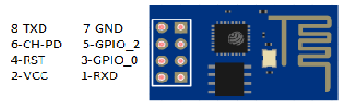
Step 3: ESP8266 Pinouts
Step 4: Components
Arduino Uno
https://www.banggood.com/custlink/m33KGFYAzy
ESP8266 Wi-Fi Module
https://www.banggood.com/custlink/mKvKDhD2ig
LM317 Voltage Regulator
https://www.banggood.com/custlink/DvDD3Avz7E
Veroboard
https://www.banggood.com/custlink/m3G3mnGz7P
Male to male jumpers
https://www.banggood.com/custlink/GKvKmAGkuQ
1uF electrolytic capacitor
10uF electrolytic capacitor
Step 5: Schematic

As ESP8266 Wi-Fi module communicate with Arduino or any other microcontroller using serial communication and it has required 3.3V minimum to run. Arduino’s 5V output will be connected to LM317 input as shown in figure
ESP8266 Connections
ESP8266 =================Connections
RXD =====================Arduino’s I/O Pin 3
VCC=====================LM317 Output
CH_PD===================LM317 Output
GND=====================Arduino’s GND
TXD=====================Arduino’s I/O Pin 2


