

Introduction: Handy Pager: an STM32 Arduino Based Pager Using Blues Wireless Cellular Notecard


Pagers are electronic devices primarily employed by individuals who are unwell or have disabilities to get in touch with their caregivers. While pagers are not a recent innovation and have a long history, the focus of this project is to cater to individuals with mobility challenges, particularly those affected by muscle dystrophy.
This is a quote from someone suffering from muscle dystrophy, that motivated me to make this project.
"So I typically only use the pager when I'm lying in bed. My arm mobility is incredibly limited in that position so even if it was attached to me by a strap I still would have difficulty getting it in a position I could use. If there was a strap that went around one of my fingers for example and the farthest the device could fall was in my palm that might work."
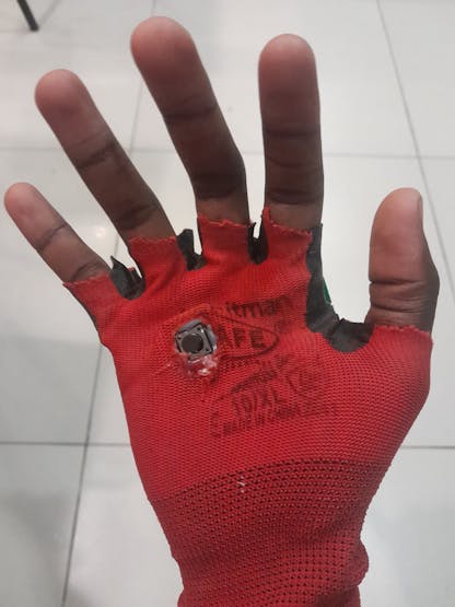
So I decided to take up the challenge and build a pager that can be worn as a glove with a button in the palm region of the glove, which when pressed sends a text message to his caregiver notifying them that he needs help.

Supplies
Hardware Components
- Blues note carrier A
- Blues Swan
- Blues Notecard Cellular
- A pair of gloves
- Lithium-ion battery
- JST connector
- Double-sided Vero board
- Tactile switch
Software and Online services
- Platform io IDE
- Twilio SMS messaging API
- Visual Studio Code
- Blues Notehub.io
- Arduino IDE
Hand Tools and Fabrication Tools
- Soldering iron
- Solder wire
- Hot glue gun
Step 1: Setting Up the Note Card
To use the notecard, we will need to have a project on notehub. Go to the notehub website and follow the steps below
- Navigate to the Notehub Projects Dashboard.
- Click on Create Project and type in your project's name in the form that pops up.

Take note of your project UID, because notehub will use it to associate your notecard to the project we created.
Setup the Notecard
The Notecarrier-A includes two u.FL cables for cellular and GPS with one side connected to the Notecarrier and one side free.
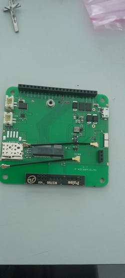
Remove the screw from the mounting receptacle on the Notecarrier and rotate the U.FL cables away from the M.2 socket.
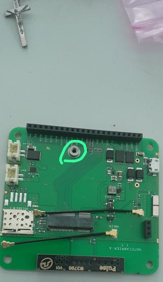
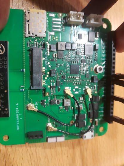
Place the Notecard into the M.2 slot on the Notecarrier. Once inserted, press gently until the Notecard is inserted and the screw receptacle hole is completely visible.
Re-insert the screw into the mounting receptacle and tighten it to secure the Notecard to the Notecarrier. Be sure to not overtighten the screw
Secure the free end of the u.FL cable connected to the socket labelled MAIN on the Notecarrier to the MAIN socket on the Notecard.
Secure the free end of the u.FL cable connected to the socket labelled GPS on the Notecarrier to the GPS socket on the Notecard.
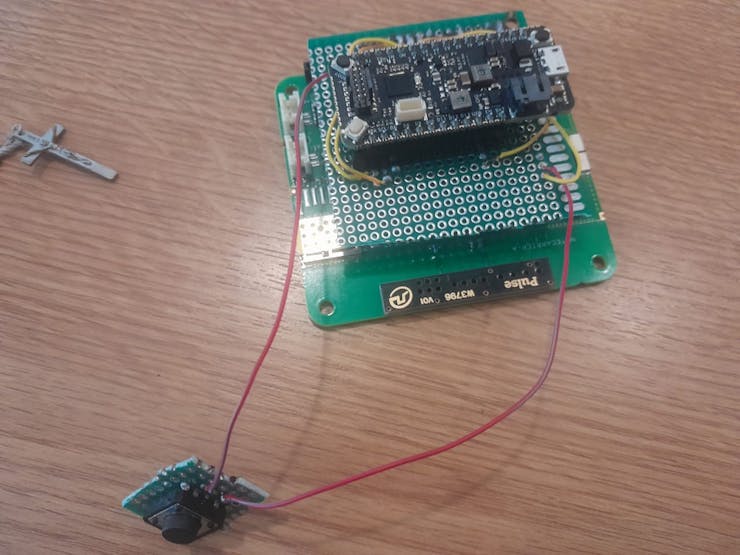
Step 2: Connecting Host MCU(SWAN)
To facilitate communication between the SWAN and the notecard, I opted for I2C communication. First, connect the SDA pin on the SWAN to the SDA pin on your notecard and the SCL pin on the SWAN to the SCL pin on the notecard. The power source for the project will be provided via a LiPo battery connected to the notecard, which in turn powers the SWAN. Ensure the MAIN pin on the notecard is linked to the VIN pin on the SWAN, and connect the ground (GND) connections.
To save power the host MCU (STM32) will be disabled, enabling it only when necessary. We achieve this by connecting the ATTN pin on the notecard to the Enable pin (EN) of the STM32. Additionally, use a push button connected to the AUX1 pin on the notecard to enable the STM32 when required. Once the STM32 completes its task, it returns to a disabled state.
For a visual representation of these connections, please refer to the provided schematic diagram.
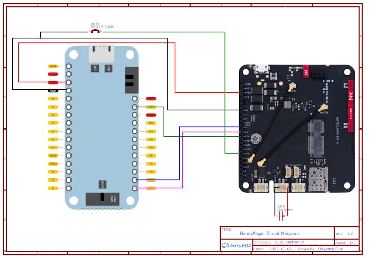
Schematic Diagram
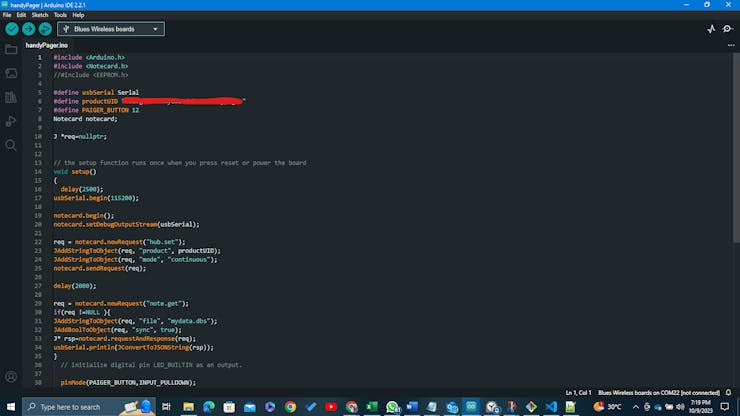
Step 3: The Code
The code's primary function is to send a text message whenever a button is pressed. I want the pager to be always on and still run on a battery so to save power, the STM32 will be disabled and when the button is pressed the STM32 is enabled, it sends the message and goes back to sleep. To understand how this works, let's delve into the code.
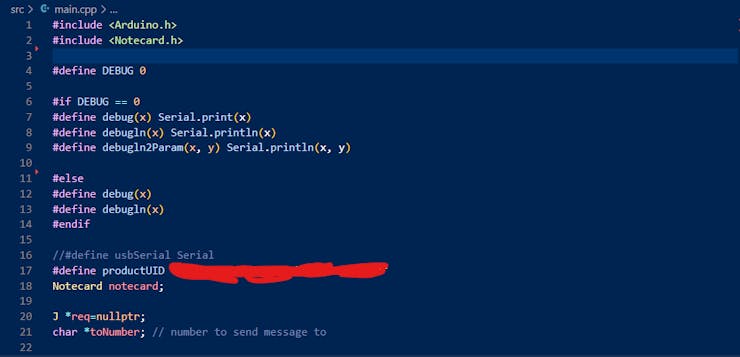
First, we define our variables
Connect to your project in NoteHub
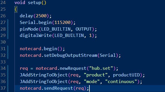
Lines 34 to 37 connect the notecard to our project to note hub using our productUID and put the notecard in continuous mode.
Get Phone Number
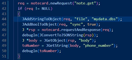
The lines of code above get the phone number that the text message will be sent to i.e. the caregiver's number, which can be changed via the mobile app.
Configure AUXGPIO
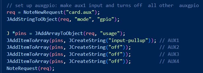
The lines of code above sets AUX1 as input and the remaining AUXs pins off. We only need one for our project.
Send the text message
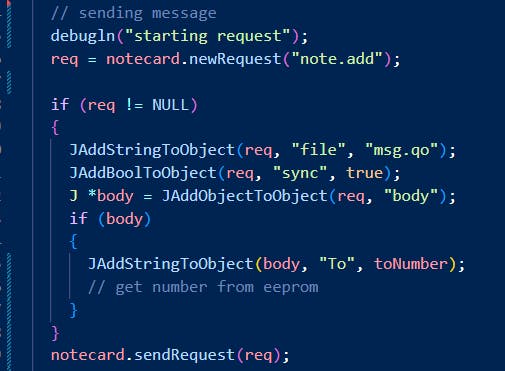
To send a message we update a note msg.qo, adding to its body the phone number we wish to send the message to.
Disable STM32
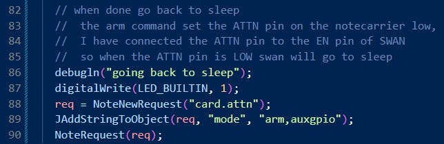
When the message has been sent I use the STM32 to send a command to arm the ATTN pin on the note carrier which sets the ATTN pin low and in turn, subsequently disables the chip, since the ATTN pin is connected to the enable (EN) pin of the STM32.
In line 89 I also add the auxgpio command which sets the ATTN pin HIGH when there is a change in its state. For this purpose, a button is connected to AUX1, such that when the button is pressed the state of the pin changes, which subsequently triggers the ATTN pin to transition to a HIGH state, thereby re-enabling the chip (STM32). This entire cycle then repeats itself.
Download the code from my GitHub repository here. If you are using platformio you can upload straight to the stm32, platformio will download all the dependencies needed. If you are using Arduino IDE you would have to install the Blues Wireless Notecard@^1.4.5 and install stm32 board. To install the board, follow the steps below
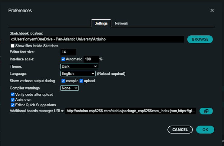
- Click on files at the top bar of the Arduino IDE and select preferences
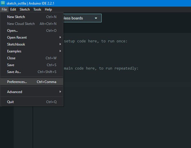
You should see the screen below
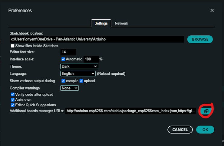
click on the icon I circled
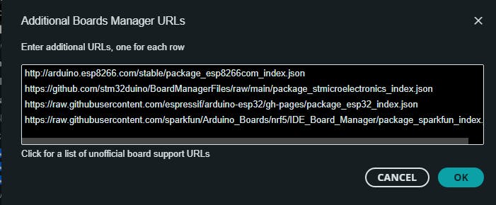
add this URL https://raw.githubusercontent.com/sparkfun/Arduino_Boards/nrf5/IDE_Board_Manager/package_sparkfun_index.json to the list and click ok.
- Click on the board manager icon on the left side of the Arduino IDE and search for STM32
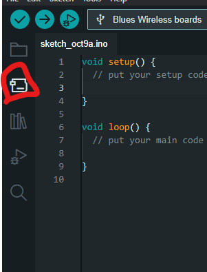
You should see the screen below
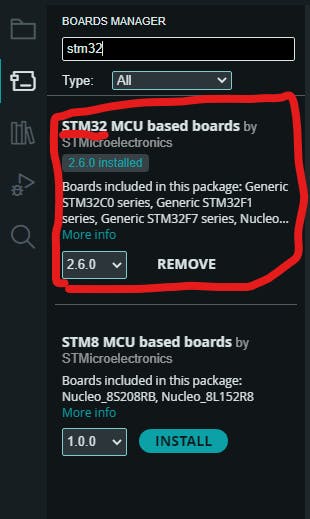
Click install to download the board, you will also need to install the stm32cube programmer, which you can download from here.
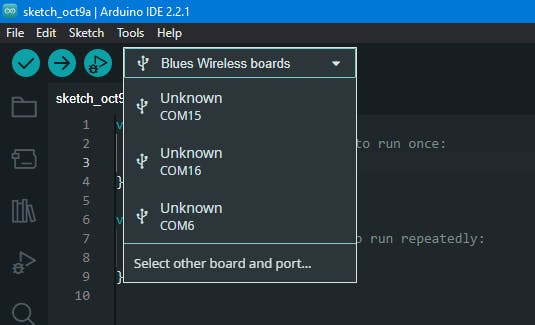
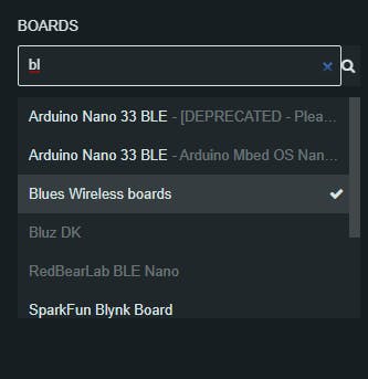
- Plug the STM32 into your computer and select your board com port from the top of the screen
its
In the directory where you've cloned the repository, navigate to the 'src' folder. Copy the contents of 'main.cpp' and paste them into a new sketch in the Arduino IDE.
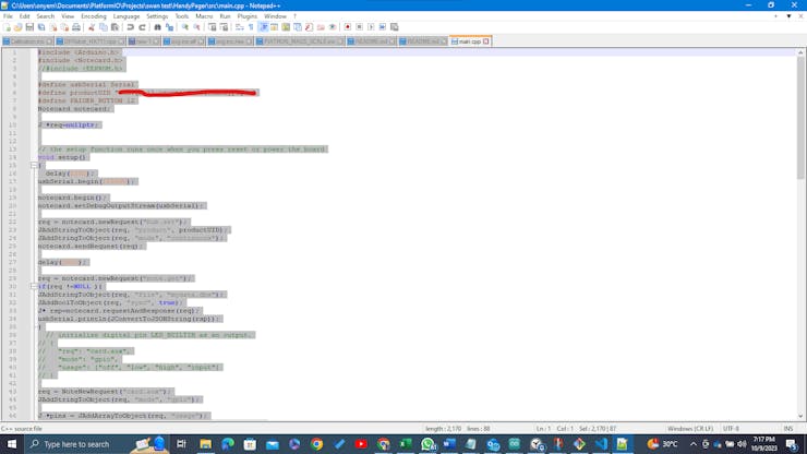
save the code and upload.
Step 4: Setting Up Your Twilio Account
- Step 1: go to twilio.com and create an account.
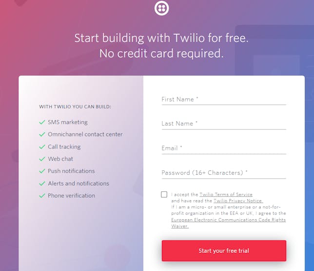
- When you are done creating an account, you should be greeted with the screen below
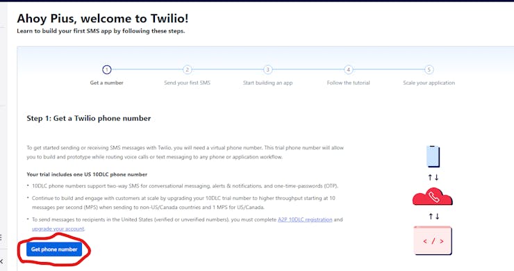
Click on 'Get Phone Number' to generate a phone number for your use. Be sure to save this phone number somewhere, as you will need it later..
- Scroll down and you see your account information
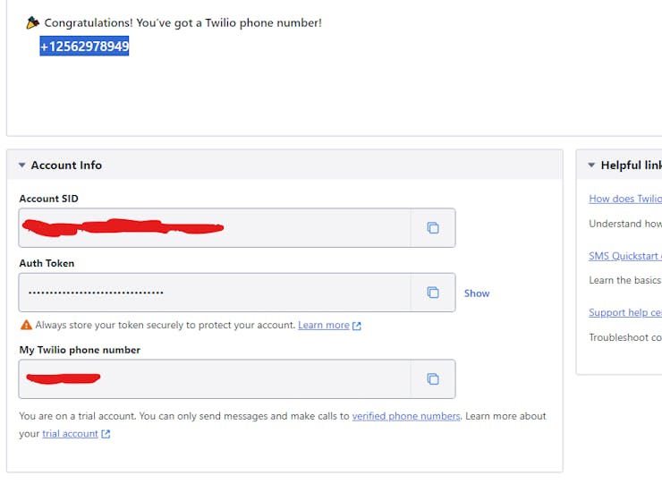
- save your account SID and Auth token somewhere also, you will need it later.
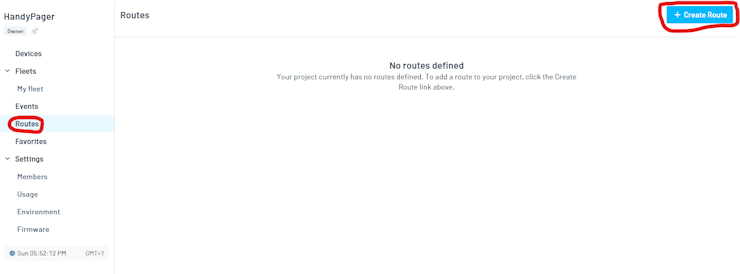
Step 5: Creating a Route
In Notehub, routes serve the purpose of transmitting data from our Notehub to external services, such as Twilio. To set up a route in your Notehub project, simply follow these steps:
1. In your Notehub project, go to the left sidebar and click on 'Routes.'
2. Then, select 'Create Route'.
Scroll down and select Twilio.

After selecting Twilio you should see the page below.
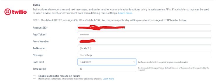
Enter your details in the respective text boxes. However, for the 'To number, ' use the syntax [.body.To], which searches for the 'To' key in the body of the note associated with the route and automatically populates the 'To Number' text box with the value stored in the 'To' field. This field is crucial for holding the recipient's phone number to which the message will be sent.
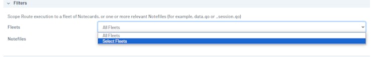
Scroll down to filters click on the fleets drop-down and choose "Select fleet"
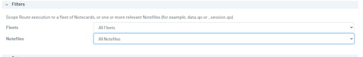
click the checkbox on "My fleets" or whatever name you gave your fleet.

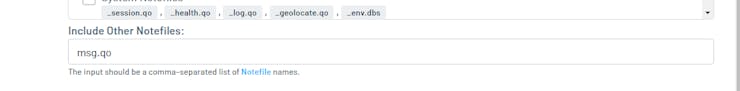
Now click on the Notefiles drop-down and select SelectedNotefiles.

unchecked any checked notefile, then go to the include other notefiles section and type in msg.qo.
Then click "Create Route" at the top right corner of the screen.
Step 6: The Mobile Application
I developed a mobile app to help change the recipient's phone number for the messages. Please note that when using a Twilio trial account, you can only send messages to the number you used to create your Twilio account.
You can access the app from my GitHub repository. If you've already cloned the repository while attempting to obtain the MCU code, you should already have the mobile application on your PC.
When you install the app and open it, you should see the Sign in page first
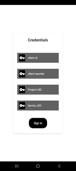
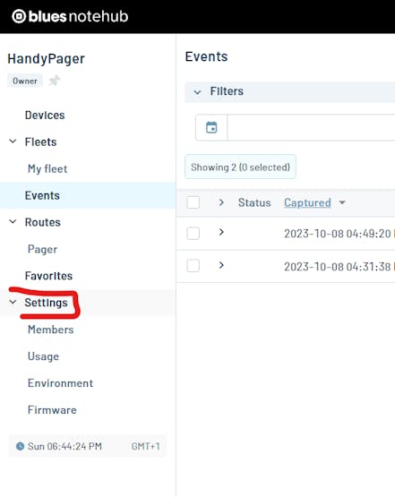
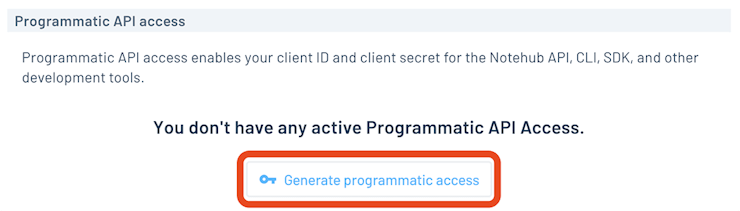
To get your project UID, click on settings in your project dashboard
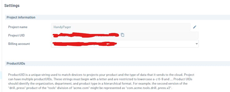
Scroll down to ProgrammaticalAPIKEY
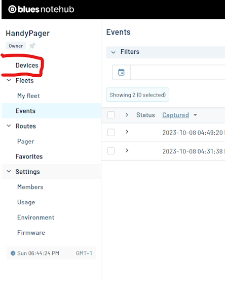
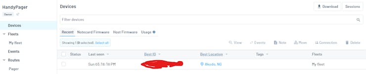
To retrieve your device UID, navigate to the 'Devices' section, and you'll find your device UID listed under your specific device.
Next, click the 'Sign In' button. You should be directed to the next screen, where you can input the phone number of the intended recipient for the text message.

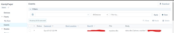
Enter the phone number, and then click on 'Submit.' If you navigate to the 'Events' section, you should observe a new note titled 'mydata.dbs' that contains the phone number you sent via the mobile application.
Step 7: Fabrication
Creating this setup is a breeze. I simply soldered the components onto a double-sided Vero board, affixed it to the back of the glove, and positioned the button right in the centre of the palm.

Step 8: Video Demonstration
Step 9: Code
You can get the code and the mobile app from the GitHub repository here.

Participated in the
Anything Goes Contest


