Introduction: How to Build a CubeSat With an Arduino With an Arducam
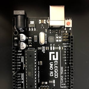

In the first picture, we have an Arduino and it is called "Arduino Uno."
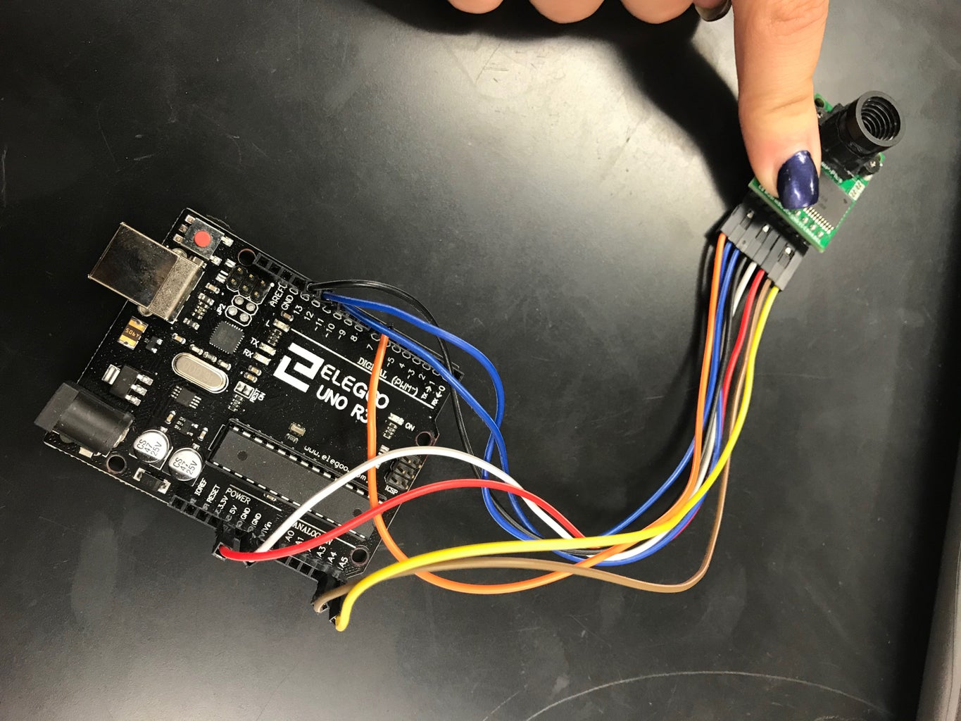
In the second picture, we have an Arducam, and it is called "Arducam OV2640 2MP mini."
Along with the second picture, there are the materials you will need to wire the Arduino and the Arducam. You will need at least 10 wires, one Arducam, and one Arduino.
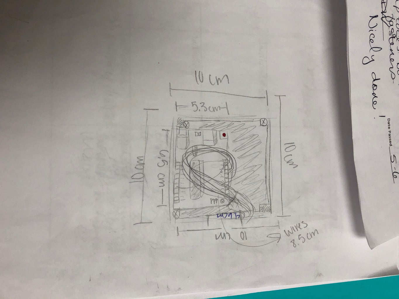
In the third picture, we have the Arduino Wiring Diagram that you will use to wire the Arduino.
~These are the items you will need to start wiring the Arduino.
~ Dhruvi
Step 1: Research Design for CubeSat

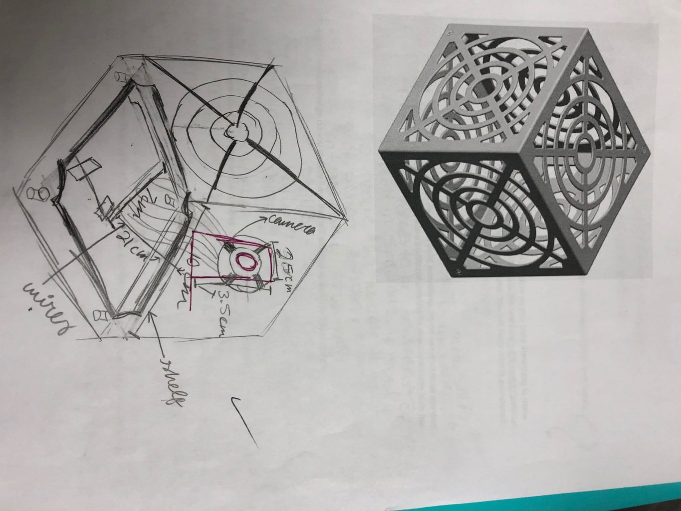
1.) Research about CubeSats and find a CubeSat design that you like. Make sure that the design you choose has an stl file (a.k.a. a printing file).
2.) Once you find a design with a .stl file make sure you have a flash drive with you, so you can download the stl file.
3.) If you are having a hard time finding a design we used this design: https://grabcad.com/library/triof-1u-cubesat-1
~ Esther Kilishek
Step 2: 3D Print CubeSat

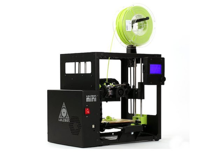
1.) If you are new to the 3D printer here is a blend space that contains videos that will help you figure out how to get more comfortable with the printer: https://www.tes.com/lessons/DIS5xKKNS62qtw/introd...
2.) Once you are familiar with the printer make sure to download the Cura software:
3.) After downloading it, plug the computer into the 3D printer. Then clean the print plate and apply a layer of glue with a glue stick so that the ink would stick to the plate.
4.) After you put the ink in the cartridge, turn on the 3D printer and wait till the printer is warmed up to start.
5.) Then you wait for it to print but be sure to come back and watch the pieces of the CubeSat if you printed it in multiple parts. If you are printing in multiple parts make sure that you apply glue before you start printing the next part.
6.) Then after all the parts are finished printing turn off the printer and clean the plate for the next group.
~ Esther Kilishek
Step 3: Wire Arducam and Arduino

- When connecting the ArduCam to the Arduino you will need 8 wires. red, 2 blue, white, orange, brown, yellow, and black.
1.) Plug the one side of the yellow wire into the first slot on the ArduCam and the other side into the Arduino at A5 to the left side of the microcontroller (AKA the brain of the Arduino).
2.)Then take one side of the brown wire and plug it into the ArduCam right next to the yellow wire. Put the other side of the brown wire into A4 right next to the yellow wire.
3.)Then take the one side of the red wire and plug into the ArduCam right next to the brown wire. Then take the other side of the red wire and plug it into 5V on the left side of the brain.
4.)Then take the one side of the white wire and plug it in next to the red wire in the ArduCam. Take the other side of the white wire and plug it into the Arduino at GND on the left side of the brain.
5.)Then take the one side of the black wire and plug it into the ArduCam right next to the white wire. Take the other side of the black wire and plug it into pin 13 in the Digital pins.
6.)Take the 1st blue wire and plug it into the ArduCam right next to the black wire. Take the other side of that blue wire and plug it into digital pin 12.
7.)Take the last blue wire and plug it into the ArduCam right next to the 1st blue wire. Then take the other end of that blue wire and plug into digital pin 11.
8.)Then finally take the orange wire and plug one side into the ArduCam right next to the 2nd blue wire. Then take the other side of the orange wire into digital pin 10.
9.) So finally you will have your ArduCam correctly wired up to the Arduino. Once you have it wired plug it into the USB cable. Then plug the other end of the USB cable into your computer and begin your research for code.
~ Britnee Miller
Step 4: Research Code for Arduino & ArduCam Based on You Project Goal

1.) When getting the code for the arducam got to https://github.com/ArduCam/Arduino. Then click the Clone or Downloaded button the the right side of the screen (it should be green). Once you have it downloaded you need to save it to your program files(x86) in the O-Drive. Make sure you label it Arducam Code.
2.) Once you have the file saved open up Arduino IDE. Once the IDE is open go to Sketch at the top of the page, then Include Library. Then Click add Zip Library. Once you do all that it should take you to your files. Once they are opened go to your O-Drive and open Program files(x86). Then click on the Arduino Code file you just saved to your computer.
3.)Once you have done that then open IDe back up again. Click File> Examples. Then scroll all the way down till you see arducam. It will then take you to that file. Once that file is opened you're gonna go to Mini>Examples>ArduCAM_Mini_2MP_Plus_VideoStreaming.inodata. Once you have clicked that it should open in Arduino IDE. once you see the code in IDE press Verify. If there are any errors then you did something wrong. Go back and read this step by step. If you got no errors then press upload.
4.) Once you have uploaded the code to your Arduino got to: files> O-Drive>Program Files> Arduino> Libraries> Arducam>Examples>Host_App>ArduCam_host_V2.0_Windows>Arducam_Host_V2
~ Britnee Miller
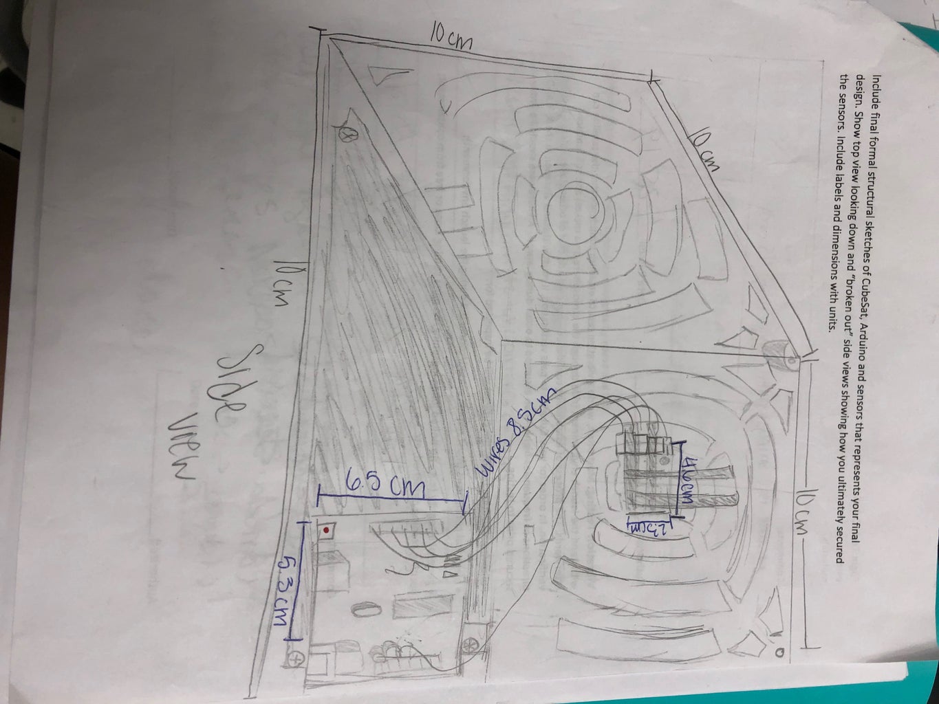
Step 5: Connect Arduino to the Shelf and Then to the CubeSat


First, drill holes in the bottom of the CubeSat. On our CubeSat, there were 4 pillars that we drilled into. Be sure you make sure that the screw that you are using fits into the hole you make. We drilled 3 holes a felt it was sturdy enough but if you feel yours needs to be sturdier you can drill more holes.
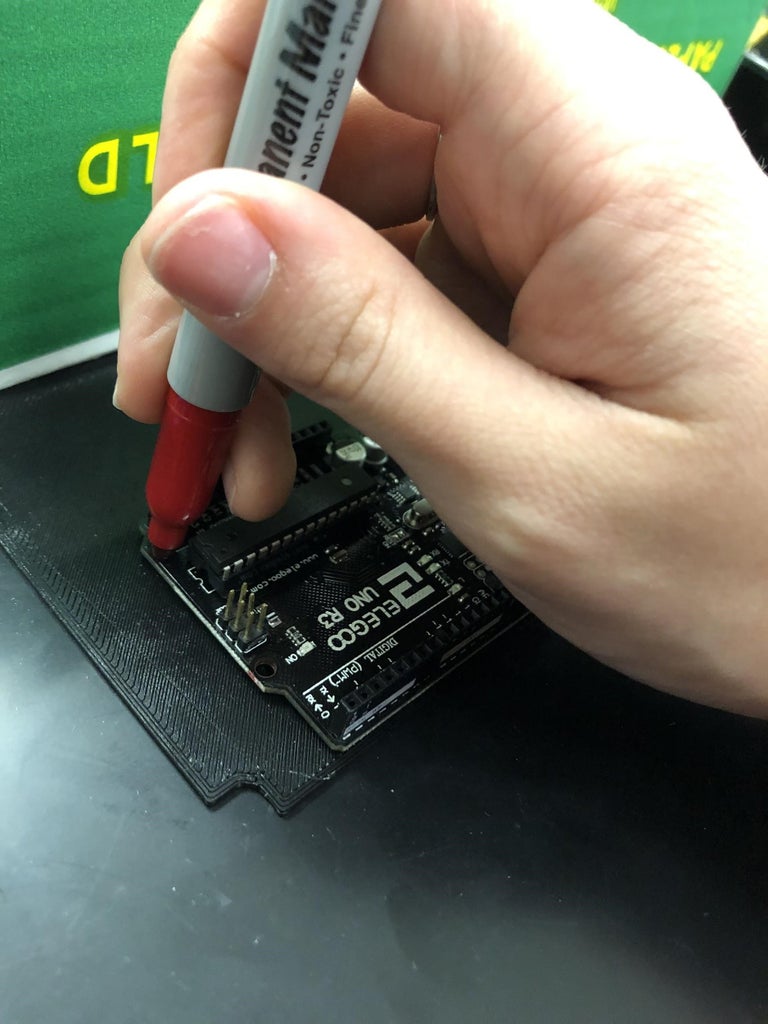
Next, mark where the holes you drilled on the CubeSat will be on the shelf so that the holes on both the shelf and the CubeSat matches up with each other after you drill.
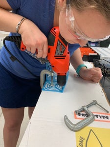
Now it's time to drill the holes where you just marked on the shelf.
Now its time to drill the holes where you just marked on the shelf. After this, you need to get ready to screw the Arduino onto the shelf. First mark where to drill the shelf to secure the Arduino. There should be holes already in the Arduino. Just line up the Arduino where you want it on the shelf and mark where the holes line up with it.
Now, drill the holes you have marked.
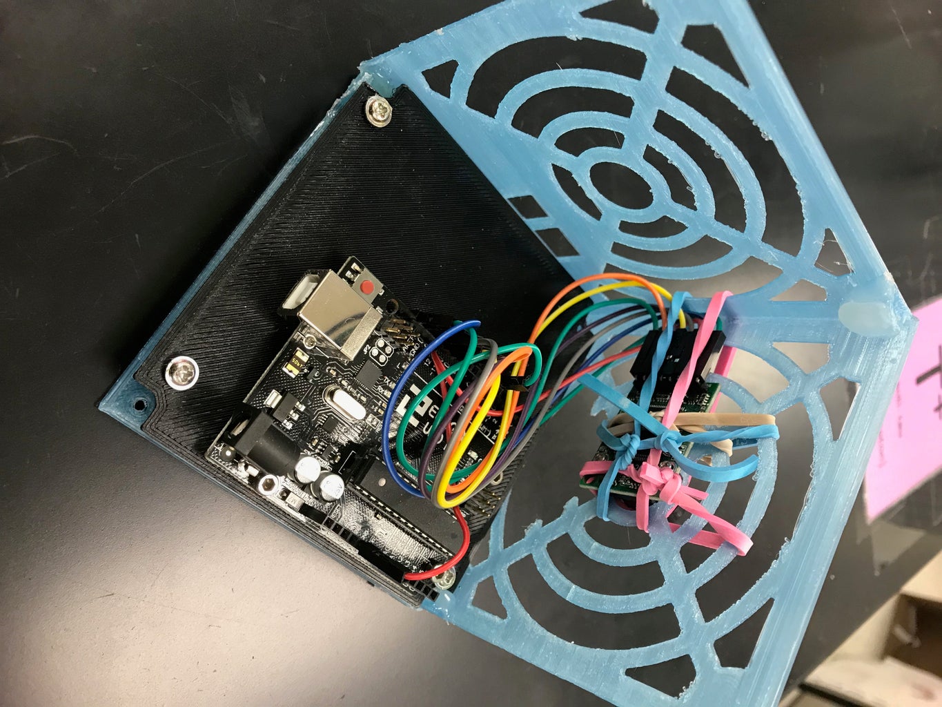
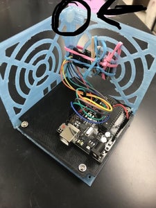
Next, screw the Arduino to the shelf and secure the screws by putting bolts on the other side of the screw.
After this, screw the shelf to the CubeSat.
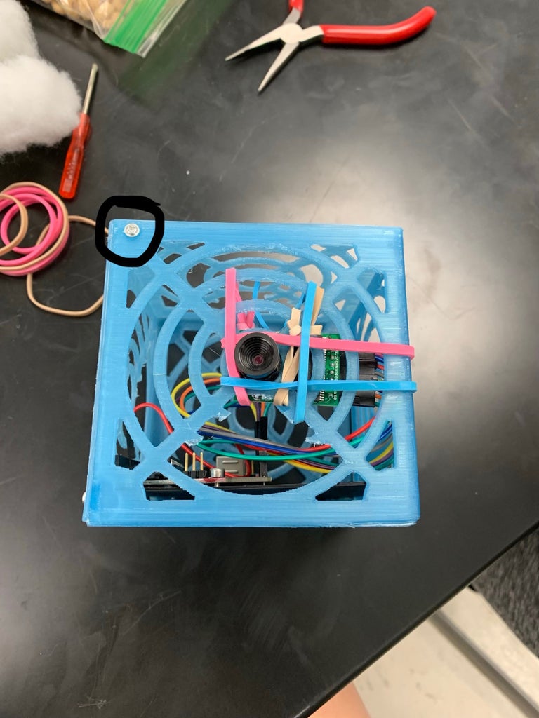
Now, attach the Arducam to the side of the CubeSat using rubber bands
~ Emma Robertson
Step 6: Put CubeSat Together

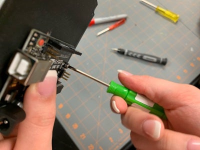
First, super glue the corners of the CubeSat where you will be screwing into.
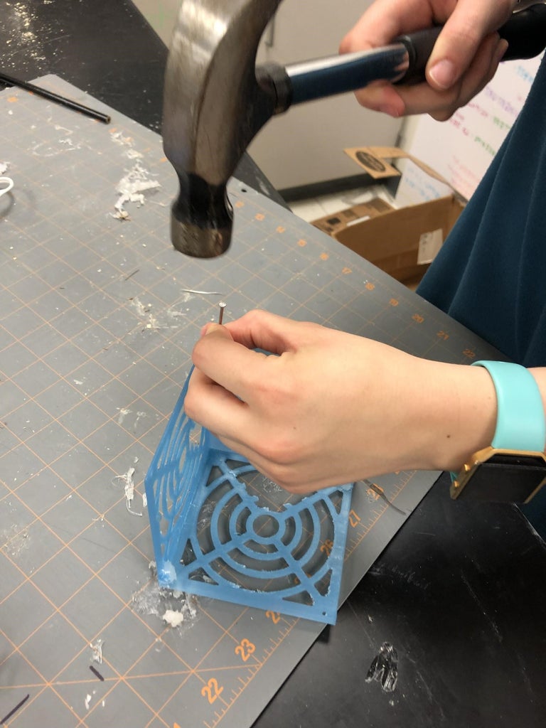
Then, hammer a nail into the super glue and make sure the hole is big enough for the kind of screw you are using. If you haven’t figured it out yet, this is how you will screw the CubeSat together.
Next, screw the CubeSat together.
Now, you are DONE!
~ Emma Robertson
Step 7: Preliminary Tests
Flight Test:
In order to find the data for the flight, we had to make sure the CubeSat was put together. Then we had to attach a string. The length of the string is your choice however we highly recommend .58 -.78 meters. Then we tied the string to the top of our CubeSat so that the camera in the cubesat is looking down at an angle. Once the string was tied we took it over to the Orbiter and connected the other side of the string to a carabiner by tieing it. then we had to turn the Variac on. Once the Variac was on, we had to turn the speed to about 125 for 30 seconds. Make sure to record the flight test in slow motion. The flight test is used to help predict what the CubeSat will do on the final data collecting test.
Shake Test:
In order to find the data for the shake test, we had to make sure that the CubeSat was put together. Then we took it over to the shake table and put it inside the box that was attached by binder clips. Then we turned on the shake table machine. In order for the table to start shaking, we had to turn the knob up to 25 volts for 30 seconds. Make sure you record your CubeSat on the shake table in slow motion so that you can find the velocity of the shaking. To find the velocity of your CubeSat you have to take distance divided by time. So the distance would be how many times the cubesat shook back and forth. Then, divide that by the amount of time you let it shake for, which should be 30 seconds. So, your data would look like this: 108 (amount of time it shook back and forth) /30 (seconds)= 3.6. The velocity of our CubeSat was 3.6 meters per second.
Space Simulation:
In order to get the data for the space simulation, we had to make sure that we had power to our Arduino before we put it on the machine. Then we put it on the space simulator and turned it on. Once the simulator was on we had to put it to 40% vibration. What that does is, it shakes the cubesat back and forth like it is in space, it's a simulation simulating how it would work in space. What this determines is wheater the power to the Arduino is still connected after the shake. We had to leave it going for one whole minute.
~ Dhruvi Patel

Step 8: Final Data Collection (Analysis)


To get the final data, we used a 15-foot long USB cord and plugged it into the USB port. We used the 15-foot long cable, to collect data, we hooked up one end to a computer and the other end to the Arduino. Then just like the preliminary flight test, we hooked it up to a carabiner and let it spin for 30 seconds on around 125 (Variac).
And this is what we measured:
Time- 1 second (for each spin)
Radius- 0.30 meters
Mass- 0.12 kilograms
Frequency- 1 hertz (1 spin per second)
Velocity- 1.88 meters per seconds
Tension Force- 0.8771 newtons (N)
Centripetal Acceleration- 11.78 meters per second squared
Centripetal Force- 1.41376 newtons (N)
~ Dhruvi Patel
~ Esther Kilishek
~ Emma Robertson
~ Britnee Miller
Step 9: The End


So in conclusion from
Britnee Miller
Dhruvi Patel
Emma Robertson
Esther Kilishek
We all hope you have as much fun as we did doing this project