Introduction: How to Build a Cubesat With an Arduino and Accelerometer.

Our names are Brock, Eddie and Drew. The main goal for our Physics Class is to travel from Earth to Mars while simulating the orbit around Mars using a Cube Sat and collecting data. Our groups goal for this project is to collect data using an accelerometer sensor that will be attached to our Arduino inside of a Cube Sat which will orbit "Mars" to find the gravitational force on that planet. Some possible constraints for this specific task would be the code not working the correct way, the accelerometer not gathering data and the limit the CubeSat can weigh. Although there are many others any person could encounter, those were the ones our group faced. A video of our final project and testing can be found here https://youtu.be/u1_o38KSrEc -Eddie
Step 1: Materials List


ALL MATERIALS LISTED GO INSIDE CUBESAT
1. Arduino & Power Cable https://www.amazon.com/Elegoo-EL-CB-001-ATmega328...
: arduino is designed to make electronics more accessible to artists, designers, hobbyists and anyone interested in creating interactive objects or environments
: allow power to and from your Arduino and computer
2. Breadboard https://www.amazon.com/Breadboard-Solderless-Prot...
: a board for making an experimental model of an electric circuit
MATERIALS ATTACHED TO BREADBOARD
1. Arduino Accelerometer https://www.amazon.com/MPU-6050-MPU6050-Accelerom...
:an instrument for measuring acceleration or for detecting and measuring vibrations
2. Arduino SD Card Module https://www.amazon.com/HiLetgo-Adater-Interface-C...
:it allows you to add mass storage and data logging to your project
3. Arduino Wires https://www.amazon.com/EDGELEC-Breadboard-Optiona...
:transfers code throughout Arduino and breadboard
4. LED Light https://www.amazon.com/Diffused-Lighting-Electron...
:an LED is a small light (it stands for "light emitting diode") that works with relatively little power
-Drew
Step 2: Tools Needed and Safety Practices
TOOLS NECESSARY
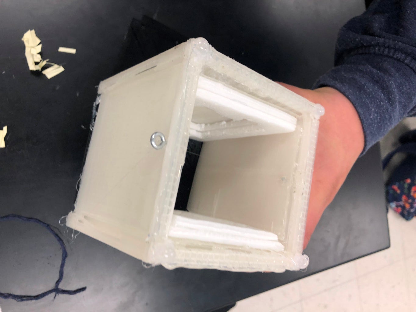
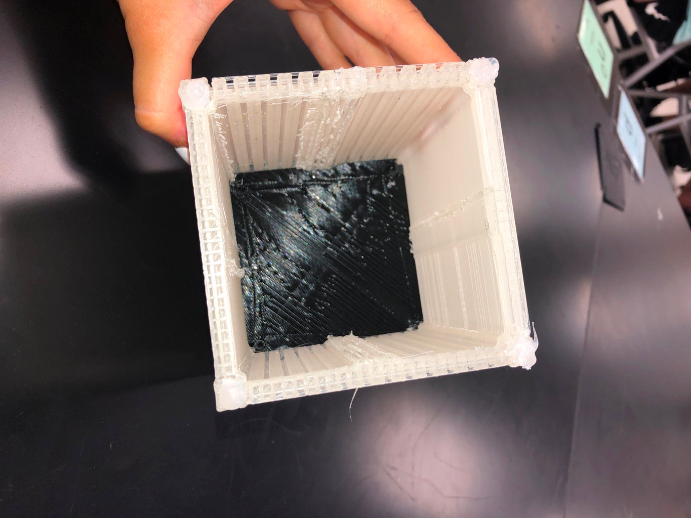
1. Exacto Knife
- we used an exacto knife to cut and trace the shape of the Arduino and Breadboard through Styrofoam, to protect the Arduino and Breadboard incase there are accidents
2. Hot Glue Gun
- we used a hot glue gun to glue the Styrofoam to the sides of our Cubesat to ensure our Arduino and Breadboard are secure
3. Styrofoam
- we used pieces of Styrofoam to secure the Arduino and breadboard to the sides of our Cubesat, also to allow a cushion if Cubesat is dropped or shaken around
SAFETY PRACTICES
1. the first safety practice we enforced was making sure we did not touch the 3D printer when it was printing the Cubesat. the 3D printer will get very hot and its important to remember to not touch it.
2. when using the exacto knife to cut out the pieces of Styrofoam, we had to place cardboard underneath to ensure the tables weren't being damaged. we also had to wear goggles when using the knife incase anything flew up in our faces or around our work space.
3. when using any tools that require hard labor, make sure to wear goggles for safety purposes.
4. once you attach the Cubesat to the orbiter, make sure to warn people around the orbiter that you will be testing your Cubesat and wear goggles to ensure all body parts and people are safe.
-Drew
Step 3: How To:

How to build a CubeSat:
1. to begin the CubeSat building process, you need to search models of the CubeSat that are 10x10x10 and have a STL file handy.
2. when you have found a model that will work in holding a breadboard and an Arduino safely, you need to download the files on a flash drive so you can access the files on the 3D printer.
3. after the correct files have been downloaded on the flash drive, you can hook up the flash drive to the computer that is hooked up to the 3D printer.
4. when you are printing, make sure you select the correct files and all the wires, codes, and inputs are correctly wired between the computer and 3D printer. this will ensure the CubeSat is printed correctly, and everything goes according to plan.
5. assign each group member a designated time to efficiently check on the printer and CubeSat progress to catch any problems you may run into. being able to have a team member check on the progress about every 2-3 hours, will provide enough assistance to fix any issues and watch the progress that will be made.
-Eddie
THE CODE:
#include
#include #include #include
const int MPU=0x68; int16_t AcX,AcY,AcZ,Tmp,GyX,GyY,GyZ; double pitch,roll;
File Data;
void setup(){
pinMode (10,OUTPUT); //must set pin 10 to output even if not used ; //setting pin 7 to light up led SD.begin(4); //begins sd card with CS set to pin 4 Serial.begin(9600); Serial.println(F("BMP280 test")); Wire.begin(); Wire.beginTransmission(MPU); Wire.write(0x6B); Wire.write(0); Wire.endTransmission(true); Serial.begin(9600); } void loop(){ Wire.beginTransmission(MPU); Wire.write(0x3B); Wire.endTransmission(false); Wire.requestFrom(MPU,14,true);
int AcXoff,AcYoff,AcZoff,GyXoff,GyYoff,GyZoff; int temp,toff; double t,tx,tf;
//Acceleration data correction AcXoff = -950; AcYoff = -300; AcZoff = 0;
//Temperature correction toff = -1600;
//Gyro correction GyXoff = 480; GyYoff = 170; GyZoff = 210;
//read accel data AcX=(Wire.read()<<8|Wire.read()) + AcXoff; AcY=(Wire.read()<<8|Wire.read()) + AcYoff; AcZ=(Wire.read()<<8|Wire.read()) + AcYoff;
//read temperature data temp=(Wire.read()<<8|Wire.read()) + toff; tx=temp; t = tx/340 + 36.53; tf = (t * 9/5) + 32;
//read gyro data GyX=(Wire.read()<<8|Wire.read()) + GyXoff; GyY=(Wire.read()<<8|Wire.read()) + GyYoff; GyZ=(Wire.read()<<8|Wire.read()) + GyZoff;
Data = SD.open("Log.txt", FILE_WRITE); //opens file called "Log"
//get pitch/roll getAngle(AcX,AcY,AcZ);
//send the data out the serial port Serial.print("Angle: "); Serial.print("Pitch = "); Serial.print(pitch); Serial.print(" | Roll = "); Serial.println(roll);
Serial.print("Temp: "); Serial.print("Temp(F) = "); Serial.print(tf); Serial.print(" | Temp(C) = "); Serial.println(t);
Serial.print("Accelerometer: "); Serial.print("X = "); Serial.print(AcX); Serial.print(" | Y = "); Serial.print(AcY); Serial.print(" | Z = "); Serial.println(AcZ);
Serial.print("Gyroscope: "); Serial.print("X = "); Serial.print(GyX); Serial.print(" | Y = "); Serial.print(GyY); Serial.print(" | Z = "); Serial.println(GyZ); Serial.println(" ");
Data.print(pitch); Data.println(roll);
Data.print(tf); Data.println(t); Data.print(AcX); //writes acel data to file Data.print(","); //prints comma in file Data.print(AcY); Data.print(","); Data.print(AcZ); Data.print(","); Data.print(GyX); Data.print(","); Data.print(GyY); Data.print(","); Data.println(GyZ);
delay(1000); }
//convert the accel data to pitch/roll void getAngle(int Vx,int Vy,int Vz) { double x = Vx; double y = Vy; double z = Vz;
}
}
THE CODE (CONT.):
-this is the code we used to gather data from the accelerometer and SD Card.
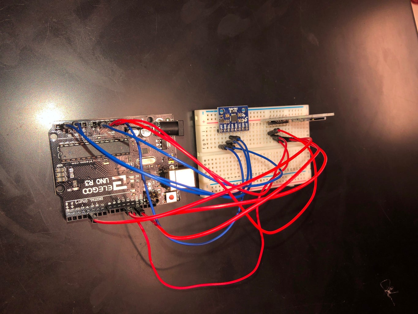
-after wiring our Arduino and Breadboard to look like the one on the frizting diagram, we plugged the SD Card into the SD Card Adaptor Module and continued getting ready for our final testing.
-we had issues with the code for a long time, but the code given above is the final code we used that gave us the data we used for our presentation.
-this code collects the data from the accelerometer and transfers the information into the SD card.
-the SD card was plugged into the USB and plugged into the computer. from there the information was put into our computer.
-Brock
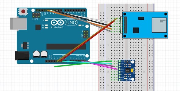
WIRING THE ARDUINO:
- while wiring the Arduino, we struggled with dud wires and dud Arduinos.
- we had to correct the wiring of our Arduino multiple times due to incorrect wiring.
- in order to ensure correct wiring and coding, make sure your wires are secured entirely and your code process correctly.
FRITZING DIAGRAM:
- the fritzing diagram was straight forward and easy to follow along with
- we faced issues with the diagram when the SD Card Module was not a part of the fritzing program. because of this, we had to search online for a downloadable part to include on the diagram
- we had completed the diagram by including the correct parts and programs into the diagram
-Drew
Step 4: Results/Lessons Learned
Our graph shows a clear rise in temperature, likely due to the heater taking time to reach the maximum temperature.
For this project, the physics we ran into was the centripetal force keeping the CubeSat orbiting.
-Brock
Step 5:

Participated in the
Arduino Contest 2019


