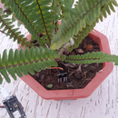
Introduction: How to Connect Soil Moisture Sensor and ESP8266 to the AskSensors IoT Cloud
This instructable shows you how to connect your soil moisture sensor and ESP8266 to the IoT cloud.
For this project we will be using a node MCU ESP8266 WiFi module and a soil moisture sensor that measures the volumetric content of water inside the soil and gives us the moisture level as output. Measurements will be monitored over the cloud using a user friendly IoT platform called AskSensors.
So let’s start!
Step 1: Moisture Sensor Specifications
The soil moisture sensor consists of two probes that allow the current to pass through the soil and get the resistance value to measure the moisture value.
The FC-28 sensor is equipped with both analog and digital output, so it can be used in both analog and digital mode. In this article, we are going to interface the sensor in analog mode.
Here are the main specifications of the soil moisture sensor FC-28:
- Input Voltage: 3.3V to 5V
- Output Voltage : 0 to 4.2V
- Input Current : 35mA
- Output Signal: Both Analog and Digital
Step 2: Hardware Requirements
- Computer running Arduino software. It is recommended to work with a new version of Arduino IDE. I'm using the v1.8.7.
- ESP8266 development board. I'm using an ESP8266 Node MCU v1.
- Soil moisture sensor FC-28 (probe + amplifier).
- USB micro cable to connect the node ESP8266 to the computer.
- Jumper wires
- Breadboard
Step 3: Pinout & Connections
Below are the three connections diagram for connecting the soil moisture sensor FC-28 to the ESP8266 in analog mode.
- VCC of FC-28 to 3.3V of ESP8266
- GND of FC-28 to GND of ESP8266
- A0 of FC-28 to A0 of ESP8266
On the other side, connect the two pins from the probe to the two pins on the Amplifier circuit via jumper wires.
Step 4: Sensor Setup
- The first thing you will need to do is to create an AskSensors account. Get your new account here. It takes few seconds.
- Register a new Sensor as explained in this getting started guide. add two modules to your sensor to store data in:
- Module 1: for moisture Level measurement.
Module 2: for moisture state. It shows an alert when the moisture level exceeds a predefined threshold.
- Copy down your Sensor API KEY IN. This is a unique Key that we will use later to send data to our Sensor.
Step 5: The Code
Get this demo code from the AskSensors github page.
Set the following parameters:
- The WiFi SSID and password
- Your Sensor API KEY IN.
const char* wifi_ssid = "......................";             // SSID
const char* wifi_password = "......................";         // WIFI
const char* apiKeyIn = "......................";      // API KEY IN
The analog output of the moisture sensor is used to connect the sensor in the analog mode (values from 0 to 1023). The moisture measurement will be converted to percentage values from 0% to 100%.
Step 6: Set Alert Threshold
The Soil moisture sensor contains a potentiometer which will set the threshold value, which will be compared by the LM393 comparator and according to this threshold value the output LED will light up and down .
However, in this demo, we will not use this potentiometer. Instead we will be using an AskSensors graph to show if the moisture value has exceeded a software predefined threshold:
#define MOISTURE_THRESHOLD 55 // moisture alert threshold in %
Step 7: Power Up Your Setup
- Connect your moisture Sensor to the ESP8266 as shown previously.
- Connect your ESP8266 to your computer via USB.
- Open your code in Arduino IDE. Choose the appropriate board and port from Arduino IDE and upload the code.
The enclosed images show my setup. For simplicity, I'm using a cup of water to test the moisture changes.
Now we should be ready to see our data in the cloud !
Step 8: Run the Test
- Return back to your sensor dashboard on AskSensors,
- Click on 'visualize' and 'Add Graph' and select Line as graph Type for Module 1 (moisture level) and Binary for Module 2 (moisture alert state).
- You can customize the Binary Graph to show up the text you want by setting the ON/OFF labels on the Add/Edit graph window.
Step 9: Results
The images shows the data read on the AskSensors graph. We can notice two cases:
- Where the sensor is out of water: The moisture value exceeds the threshold and the Alert is set (as shown in the Binary graphs.
- Where the sensor is in water: The moisture level is OK.
Now open a serial terminal on your Arduino IDE. You can cross-check the AskSensors graph readings with the values being printed on your Arduino Terminal.


