Introduction: How to Create a Vise Assembly on Inventor

Background Knowledge:
When creating an Assembly you must understand the concept of the 6 degrees of freedom. In the application we will only be using three of them: X, Y, and Z. When placing parts within the assembly we must lock them into place by setting the part's X, Y, and Z making it to where that part cannot move. This is how you correctly place parts within an assembly by eliminating it's degrees of freedom. With this knowledge we can continue on to creating our assembly. In this instructable, we will be assembling a bench vise.
Supplies
Autodesk Inventor (Any year, Photos are from Inventor 2019)
3D Models (IPT files) of all your parts needed to assembly the vise:
Base, Jaw, Key, Screw, Handle Rod, and Handle Knob
Step 1: Open an Assembly File

Step 1: Create all the 3D Models (ipts) for the Vise Assembly
Step 2: Save all the ipt files in a folder to easily be found
Step 3: Open an Assembly file
Upon starting inventor, click New in the top right and a window will open up. You will see multiple options for different types of files but one column will say assembly. Underneath that you must select standard iam as highlighted in the photo. Once selected, press the create button on the bottom right of the window. This will open a blank assembly file.
Step 2: Placing the First Part: the Base

Step 4: Place the Base
To place a part press the place button at the top right of the screen. This will prompt you to select an ipt or other inventor accepted file within your computer storage or other devices. For the first part, you want to select the main piece that all other parts will be based off of. This is usually the biggest piece and is considered the base part. Once you select your base part from your computer, the part will appear on the screen and will be attached to your mouse icon. As you drag the mouse your part will follow it. For the first part, you must right click your mouse and select place grounded on the origin. This will place the part on the origin of the file, in doing so it will eliminate all degrees of freedom locking the part down to the origin. This part is now place and we can move on to the next part.
Step 3: Adding the Second and Third (X2) Part: Jaw and Keys


Step 5: Orientate the Jaw
Step 6: Place the Jaw
Step 7: Orientate the Keys
Step 8: Place the Keys
Our third part (2 Keys) will be constrained to the second part which will be constrained to the base, so we will need to bring in the jaw and the two keys in before we move on using the place button in the top right. When bringing in any parts after the base, it is wise to orientate the parts to look like they will on the assembly to make it easier on you visually. This can be done as the part is connected to the mouse by right clicking and rotating your part 90 degrees either in the X, Y, or Z. Once you have it orientated then you can left click to place the part. I would advise to place the part away from the base and you can constrain it later to where it needs to be. This is done to visually make it easier on you as you make your assembly.
TIP: You can pan the screen by clicking your scrolling button on your mouse and rotate by holding shift and clicking the same button.
Step 4: Constraining the Keys to the Jaw


Step 9: Mate the side face of key to the side face of the channel on the Jaw
Step 10: Flush the back face of the key to the back face of the Jaw
Step 11: Mate the top face of the Key to the top face of the channel of the Jaw
Step 12: Repeat 5,6, and 7 for the Second Key
In the tool bar within inventor under the relationships tap, you will see a Constrain button. Clicking that will open a window with several constrain types. In this tutorial, we will be using the insert and mate constrain types. To attach the keys to the jaw we will be using mate. Within mate there are two extra options under the solution tab: mate and flush. Firstly using mate, we will click the face side face of the key as shown in picture two and click the face inside the channel within the jaw as shown in picture three. Then using the flush option we will clock the end of the key and the back of the jaw as shown in picture three and four. Lastly, we will use the mate to click the top face of the key and top face of the channel on the jaw. This will eliminate the three degrees of freedom locking the key into the channel. This process will be inadvertently repeated for the other key as shown in the last picture.
Step 5: Constraining the Jaw to the Base


Step 13: Mate the part grabbing face of the jaw to the corresponding face of the Base
Step 14: Flush the side face of the Jaw to the Side face of the Base
Step 15: Mate the Top face of the Key to the Key channel on the Base
To constrain the jaw to the base we will start by using the mate command clicking the front face of the jaw and base where the material will be held by the vise. On this part we will have to insert an offset to place it at the desired position. This can be seen on the first photo. Then use the flush command and click the side of the jaw and side of the base as seen in photo two. As you can see, the keys that were constrained to the jaw also move as we constrain the jaw. for the final constrain we will have to mate the top face of the key to the underside channel of the base as seen in photo three. This will fully constrain the jaw to the base at our three degrees of freedom. We can now move on to the next part.
Step 6: The Screw


Step 16: Orientate the Screw
Step 17: Place the Screw
Step 18: Mate the screw to the Jaw
Step 19: Mate the Screw to the Base
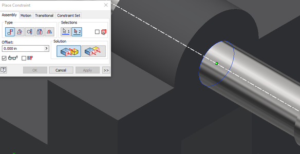
Using the place command, import the screw ipt into the assembly file and orientate it accordingly. We will then use the mate command to place this part as seen in picture two. Click the inside face of the hole on the jaw and the end of the screw. Be sure to click the inside face, shown in picture three, to ensure that the screw is placed inside the hole on the back of the jaw. We will also need to create a mate constrain between the hole on the base and the shaft of the screw as seen in picture four and five.
Step 7: Handle Rod and Knobs


Step 20: Orientate the Handle Rod
Step 21: Place the Handle Rod
Step 22: Orientate the Handle Knobs
Step 23: Place the Handle Knobs
Step 24: Insert the Knob onto the Rod
Step 25: Repeat 17 for the other Knob
Step 26: Mate the Handle to the hole on the Screw
Next we will place orientate the handle rod and knobs into the assembly file as shown in the first picture Use the insert command as shown in picture two and three to attach the knobs onto the handle. Be sure to click the bottom face of the knob to ensure that the rod goes into the knob. This assembles the handle and we will then use the mate command on the hole of the screw and shaft of the handle as shown in pictures five and six.
Step 8: Complete!

Step 27: Sit back and relax, You've made the assembly!
We now have a completed vise assembly within inventor!