Introduction: How to Power August Smart Lock From Outlet Wall Power?


Recently, my dad bought an August smart lock and installed on our garage door. Problem is that it runs on battery and my dad doesn’t want to worry about changing the battery very often. As such, he decided to power the August smart lock from the outlet wall power - in addition to its battery.
In order to do this, he needs to route DC power wire from the outlet to the smart lock. This DIY describes how he powers the August smart lock from outlet wall power and its battery, hides all wires, and provides a safe solution to not worry about burning down the house due to wire short.
This DIY will cover:
- How to automatically switch between outlet DC power and its battery?
- How to get power to the August smart lock?
- How to route power wire from the lock to the door hinge side?
- How to route power wire from the door frame to the outlet power?
- How to ensure that a short doesn't cause a fire and burns down the house?
- How to paint copper tape?
Step 1: How to Automatically Switch Between Outlet DC Power and Its Battery?

In order to power the August smart lock from wall DC power and its battery, it must have a circuit that will automatic switch between two DC sources. After searching the web, this solution seems to work. It is a simple circuit with just four surface mount components. This circuit is designed using EasyEDA - a free online PCB design tool. The printed circuit board (PCB) measures 5 x 25 mm (see picture above).
The circuit must be small to fit into the area of the August smart lock battery compartment area. To create the PCB, use the photo-resist dry film solution. There are many instructions on the web on how to build PCB with photo-resist dry film. Please note that there are various web discussion using two diodes. But the two diodes solution don't provide as a clean solution as compare to this circuit.
The circuit components include the follow:
- LTC4412 (1 - $3.44) - https://www.digikey.com/product-detail/en/linear-...
- FDN306 (1 - $0.51) - https://www.digikey.com/product-detail/en/on-semi...
- Schottky Diode (1 - $0.45) - https://www.digikey.com/products/en?keywords=1N58...
- 16V cap (1 - $0.30) - https://www.digikey.com/products/en?keywords=1276...
- Copper plate (1 - $5.98) - https://www.amazon.com/gp/product/B07DJV7PJN/ref=...
The material for photoresist dry film PCB creation is below:
- Transparency pape (1 - $9.90) - https://www.amazon.com/Inkjet-Transparency-Positi...
- Desolder Braid (1 $6.49) - https://www.amazon.com/MG-Chemicals-Clean-Super-D...
- Sodium Hydroxide (1 - $13.99) - https://www.amazon.com/FDC-99-Pure-Sodium-Hydroxi...
- Dry Film (1 - $9.59) - https://www.amazon.com/Photosensitive-Photoresist...
- Sodium Carbonate (1 - $4.17) - https://www.amazon.com/Arm-Hammer-Super-Washing-So...
- UV Light (1 - $16.99) - https://www.amazon.com/HouLight-IP65-Waterproof-8...
In order to solder these surface mount components, it is simple to use a frying pan with aluminum foil wrapped over the pan. Place the circuit board and its component with solder paste on the pan. Turn on the stove in middle heat. Don't heat up too fast as that might pop the components. Once the temperature reaches 180 degree C, the solder paste will turn silver. Then, turn off the stove. If you don't have a temperature measure gun, look at the solder paste. Once all the solder paste turns silver, you can turn off the stove. The desolder braid is used only to remove excessive solder if you add too much solder paste. Please note that these surface mount components don’t need that much solder paste. Therefore, don’t add too much.
Solder Paste uses to solder surface mount components is below:
- Solder Paste (1 - $10.99) - https://www.amazon.com/gp/product/B017RSZFQQ/ref=...
After you had created the circuit, do the following:
- Using an ohm meter to verify all the component connection to ensure no short.
- Solder a wire for the ground. On the other end of the wire, solder a nickel solder tab. The wire only needs to be around 4 inches. The nickel solder tab end will be placed between the ground of the battery and the August ground battery input.
- Solder a wire for the battery input (B+). On the other end of the wire, solder a nickel solder tab. The wire only needs to be around 2 inches. The nickel solder tab will be placed between the battery positive and the August positive input.
- Solder a wire for the power output (Out). On the other end of the wire, solder a nickel solder tab. The wire only needs to be around 2 inches. The nickel solder tab will be placed between the battery positive and the August positive input.
- In between 3 and 4 nickel solder tabs, put some place heat tape to provide insulation between these two nickel tabs. But you want to ensure #3 contacts with the battery positive lead and #4 contacts with the August positive input.
- Solder a wire for the wall power input (W+). On the other end of the wire, crimp a 1-pin dupont connector.
Material uses to connect the circuit to the battery terminals:
- Nickel Solder Tabs (dozen - $2.00) - https://www.ebay.com/itm/100-Pcs-2-5-x-0-5cm-SPCC...
- Some solid thin wire - https://www.amazon.com/Breadboard-B-30-1000-Plate...
- Heat tape (1 – $5.99) - https://www.amazon.com/Breadboard-B-30-1000-Plate...
Attachments

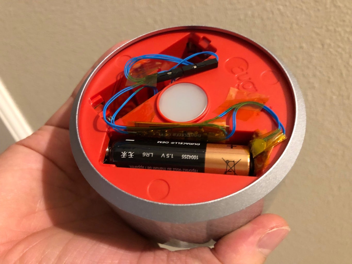
Step 2: How to Get Power to the August Smart Lock?


Now, how to route power wire from the lock to the door frame? This is achieved by using wire wrap wire and drilling hole in the August smart lock.(Please note that this will void your warranty. Do at your own risk.)
Wall power wire routing:
- Google on how to disassemble the August smart lock
- After you disassemble the lock, drill hole based on the picture above
- Then, route wire wrap wire through them
- On the August smart lock end, the ground wire will solder to a nickel solder tab. This will be sandwich between the battery negative lead and the August negative input. On the positive lead, connect to a single 1-pin dupont connector. Note that male or female is fine as long as you can mate with the battery switching circuit accordingly
- On the end out of the August lock, connect the negative and power leads to a 2-pin dupont connector.
- Make sure that the wire wrap wire is around 10 inches long. This is required so that you can connect to the lower end of the door.
Step 3: How to Route Power Wire From the Lock to the Door Frame?


Moving on, how do we route power wire from the lock to the door hinge side? This is achieved by using wire wrap wire and copper tape.
- Remove the dead bolt lock from the door
- Route the wire wrap wire through the hole. These wires are small and should be able to route them through the existent hole (without drilling additional hole)
- On the end of the wire that comes out of the door round hole, connect a 2-pin dupont connector.
- On the other end (on the side of the door), solder a Nickel solder tab for each wire.
- Then using copper tape, apply two copper tape strips around the door side and route all the way from the door knob areas to the top hinge area. The copper tape end of the door knob should wrap down to the rectangle area. You want the door knob rectangle metal plate to crimp the nickel metal tab and the copper tape. See drawing above picture.
- On the door knob area, place the nickel solder tab on top of the copper tape. See drawing above picture.
- Then install the dead bolt back. Make sure all the wires are in the correct position and that the door rectangle crimp on the nickel plate positive and negative leads accordingly.
- On the door hinge area, route the wire. See drawing above picture.
- Then, use the flat straight brace metal joining plate to crimp the flex cables. See drawing above picture.
Material uses between door and frame:
- 4 POS FPC Flex Cable 5" (2 - $1.49) - https://www.digikey.com/products/en?keywords=WM22...
- Straight Brace Metal Joining Plate (1 - $8.99) - https://www.amazon.com/eBoot-Pieces-Straight-Join...
- 1/4 inch copper foil tape (1 - $6.99) - https://www.amazon.com/Selizo-Conductive-Shieldin...
Step 4: How to Route Power Wire From the Door Frame to the Outlet Power?


To route power on the door frame, use the Micro SlimRun flat ethernet cable as follow:
- On one end, cut and strip the wire
- Use four wires for negative and the other four wires for positive
- You can strip the wire by burn them (after you remove the outer plastic)
- Then, solder one FPC flex cable to the negative and one on the positive lead. See drawing above picture.
- Take the wire and route them behind the door plastic guard, down to the floor area
- Then route underneath the frame accordingly
- The other end of the cable will connect to an Ethernet Keystone jack which then connect to a DC power jack
- The 6.5V power adapter will connect to the DC power jack
Material uses to route power to the door frame:
- Micro SlimRun Cat6 Flat Ethernet Patch Cable (1 - $7.20) - https://www.monoprice.com/product?p_id=34652
- RJ-45 Toolless 180-Degree Keystone (1 - $1.49) - https://www.monoprice.com/product?p_id=15665
- Power Jack (1 - $7.99) - https://www.monoprice.com/product?p_id=34652DC
- 6.5V 2A AC/DC Adapter (1 - $8.76) - https://www.ebay.com/itm/6-5V-2A-AC-DC-Adapter-Fo...
Step 5: How to Ensure That a Short Doesn't Cause a Fire and Burn Down the House?
In order to ensure that we don't causes a short and burn down the house, we will use a PTC resetable fuse of 24V 500mA. As this fuse is surface mount, create the PCB and solder this fuse using the same method as the above circuit. Then, solder the wire accordingly and insert this fuse between the Ethernet keystone jack and the DC power jack power positive lead. Please be aware it is between the positive lead!
Material uses to protect short circuit:
- PTC Reset Fuse 24V 500mA (1 - $0.41) - https://www.digikey.com/products/en?keywords=MINI...
For the housing of the Ethernet and DC power jack plug along with thePTC reset fuse, see this - https://www.thingiverse.com/thing:3714192.
Step 6: How to Paint Copper Tape?

After you had tested, paint the door side as follow:
- For the connection that meets the flex cable, put a small strip of tape over the copper tape before paint
- Primer the door side. There are a lot of primers. This is what I used - https://www.homedepot.com/p/Zinsser-Bulls-Eye-1-2... But after google more, may be this is a better option - https://www.homedepot.com/p/Zinsser-1-gal-B-I-N-S.... If there are quart size, buy the quart size and save some $$.
- Paint the door side
After painting, you can barely see the copper tape on the door side.
Step 7: See It in Action
URL for video later time...


