Introduction: How to Simulate a Traffic Light System With Arduino Nano


This morning I was wondering how the traffic light works, when I stared at the traffic light and waited for green light to pass the crossroad. So I make this project with some simple paper molds to illustrate. Welcome to advise!
Step 1: Prepare Materials

SunFounder Nano board http://bit.ly/2fwJNnj
2 x RGB LED http://bit.ly/2ud56B3
8 x 220Ω resistor
2 x 7-segment display
2 x 74HC595
Breadboard
USB cable
Several jumper wires
Step 2: Make the Paper Crossroad

Draw a script for the crossroad, and cut it out.
Step 3: Make the Paper Cars

Then draw two cars’ script, cut them out, and paint colors.
Step 4: Wiring for 74HC595, 7-Segment Display and Nano


First, insert the 74HC595, 7-segment display and SunFounder Nano to the breadboard, then we connect them as shown in the table.
Note: Connect the GND pin of the 7-segment display to a 220Ω resistor before grounding.
Step 5: Wiring for RGB LED and Nano
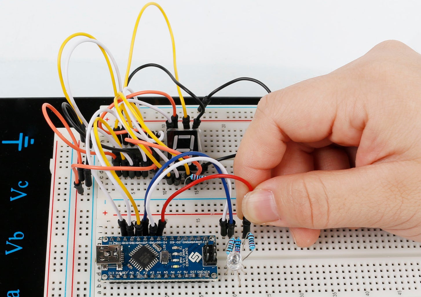

Connect the SunFounder Nano to the two RGB LEDs as the table shows.
Connect the LEDs’ GND to ground. Don’t forget to connect a 220Ω resistor between each Nano and RGB LED connections.
Note: In this experiment, we will use the blue light of RGB LED to replace the yellow light in traffic system.
Step 6: Upload the Code
The whole sketch is as follows. Upload it to the SunFounder Uno.
const int red1Pin=
5; //red1 led attach toconst int yellow1Pin =6 ; //yellow1 led attach to
const int green1Pin= 7; //green1 led attach to
const int red2Pin= 2; //red2 led attach to
const int yellow2Pin =3 ; //yellow2 led attach to
const int green2Pin= 4; //green2 led attach to
const int STcp1 = 9;//Pin connected to ST_CP1 of 74HC595
const int SHcp1 = 8;//Pin connected to SH_CP1 of 74HC595
const int DS1 = 10; //Pin connected to DS1 of 74HC595
//display 0,1,2,3,4,5,6,7,8,9
const int STcp2 = 12;//Pin connected to ST_CP2 of 74HC595
const int SHcp2 = 11;//Pin connected to SH_CP2 of 74HC595
const int DS2 = 13; //Pin connected to DS2 of 74HC595
//display 0,1,2,3,4,5,6,7,8,9
int datArray[16] = {
0, 252, 96, 218, 242, 102, 182, 190, 224, 254, 246};
void setup()
{
pinMode(red1Pin, OUTPUT); //set the redPin as an output
pinMode(yellow1Pin, OUTPUT); //set the yellowPin as an output
pinMode(green1Pin, OUTPUT); //set the greenPin as an output
pinMode(red2Pin, OUTPUT); //set the redPin as an output
pinMode(yellow2Pin, OUTPUT); //set the yellowPin as an output
pinMode(green2Pin, OUTPUT); //set the greenPin as an output
//set pins to output
pinMode(STcp1,OUTPUT);
pinMode(SHcp1,OUTPUT);
pinMode(DS1,OUTPUT);
pinMode(STcp2,OUTPUT);
pinMode(SHcp2,OUTPUT);
pinMode(DS2,OUTPUT);
Serial.begin(9600); // start serial port at 9600 bps:
}
void loop()
{
State1();
State2();
}
void State1()
{
digitalWrite(red1Pin,HIGH); //turn on a red led
for(int num = 10; num >=0; num--) //display 9-0 and turn on a green led
{
digitalWrite(green2Pin,HIGH);
digitalWrite(STcp1,LOW); //ground STCP1 and hold low for transmitting
shiftOut(DS1,SHcp1,MSBFIRST,datArray[num]);
digitalWrite(STcp1,HIGH); //pull the ST_CP to save the data
delay(1000); //wait for a second
}
digitalWrite(green2Pin,LOW);// turn off the green led
for(int num = 1 ;num >=0; num--)
{
digitalWrite(yellow2Pin,HIGH);
delay(1000); //wait for a second
}
digitalWrite(yellow2Pin,LOW);
digitalWrite(red1Pin,LOW); //the red led finally turn off
}
void State2()
{
digitalWrite(red2Pin,HIGH);
for(int num = 10; num >=0; num--)
{
digitalWrite(green1Pin,HIGH);
digitalWrite(STcp2,LOW); //ground STcp2 and hold low for as long as you are transmitting
shiftOut(DS2,SHcp2,MSBFIRST,datArray[num]);
digitalWrite(STcp2,HIGH); //pull the STcp2 to save the data
delay(1000); //wait for a second
}
digitalWrite(green1Pin,LOW);
for(int num = 1 ;num >=0; num--)
{
digitalWrite(yellow1Pin,HIGH);
delay(1000); //wait for a second
}
digitalWrite(yellow1Pin,LOW);
digitalWrite(red2Pin,LOW);
}
Step 7: Now You Get the Traffic Light System!

When the RGB1 ends Red with its countdown over, it turns Green and RGB2 turns Red and starts countdown, car1 can pass the crossroad; 110 seconds later, the RGB2 turns Yellow (here is a blue light), then turns green and RGB1 turns red after 2 seconds. Then car2 can pass the crossroad. When RGB1 turns green, it'll be like in the photo.
So that's this interesting experient. Now try your own!


