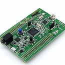
Introduction: How to Solve Clone SimpleBGC Controller Upgrade Issue
Hello. Recently, I was working over SimpleBGC gimbal controller for my drone project. I successfully connected and tuned it. It was working perfectly. After that, I wanted to upgrade its firmware from v2.2 to v2.4. So, after I upgraded the gimbal it didn't work as it should. As you know, if you have a SimpleBGC controller and if after upgrade it doesn't work, then it is not an original one. So, I decided to downgrade the firmware to v2.2 again.
I searched a lot about that. Almost all the tutorials were using Arduino as a programmer. However, while I have tried a lot this method with several Arduinos, I couldn't achive.
So, in this tutorial I will show you how to solve that issue without Arduino, but a AVR USBasp programmer, which is much easier than the Arduino. Let's see what we need for that tutorial:
1. A computer with Windows operating system. (As I have never used MAC, I don't have information about it)
2. AVR USBasp programmer which you can easily find. (Except from Azerbaijan :) ) (https://images.ua.prom.st/593769968_w640_h640_prog...)
3. Arduino IDE
4. AVRdudeR,Optiboot, XLoader (https://www.basecamelectronics.com/downloads/8bit/)
5. Download firmware (https://drive.google.com/open?id=1cM7lsf7LyAlzPrxK...)
After making your guns ready, let's jump to the tutorial :)
Step 1: Connecting Programmer to the Controller
In the first step, we have to make connection between programmer and the controller. Above you can see the pins of controller and the programmer. You have to make connection between:
RES (controller) ----------> RST (programmer)
SCK (controller) ----------> SCK (programmer)
MISO (controller) ----------> MISO (programmer)
MOSI (controller) ----------> MOSI (programmer)
SCK (controller) ----------> SCK (programmer)
+5V (controller) ----------> VCC (programmer)
GND (controller) ----------> GND (programmer)
Here, I want to add a side note. When I made these connections, I face a problem in +5V and GND connections. My controller and programmer turned off. If you face this problem too, please connect VCC and GND of the programmer to another +5V and GND pins of the controller.
After the controller and the programmer connected, then connect the programmer to the PC.
Step 2: Burn Bootloader With Arduino IDE
Open Arduino IDE and then choose USBasp as programmer. You can do this by going 'Tools' tab and come to the 'Programmer' section and choose 'USBasp'. After that, you can burn the bootloader by clicking on 'Burn Bootloader' section under 'Tools' tab. You should get successful burn message at the end!!!
Step 3: Flash the Arduino-compatible Bootloader
In this step, unzip AvrdudeR and optiboot zip files and copy 'optiboot_atmega328.hex' from optiboot folder and paste into AvrdudeR folder where 'avrdude.exe' exists. After that, open PowerShell or cmd inside this folder (you can watch how to do it from the youtube video I noted) and write these commands.
avrdude avrdude.conf -c usbasp -p atmega328p -e -u -U lock:w:0x3f:m -U efuse:w:0x05:m -U hfuse:w:0xDC:m -U lfuse:w:0xEE:m
avrdude avrdude.conf -c usbasp -p atmega328p -U flash:w:optiboot_atmega328.hex -U lock:w:0x0C:m
After you successfully run these commands, hop to the final step :)
Step 4: Upload Firmware
In the final step, open the XLoader and click XLoader.exe and include the path of 'SimpleBGC_2_2_b2_null.hex' with baud rate of 115200. Be careful, choose the correct port :)
And you have done :) If you have any problem, please write here. I will try to answer. Thank you very much :)


