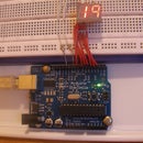
Introduction: How to Add 6 Extra Pins to Your Arduino With No Extra Hardware
Hello, this is my second Instructable so please bear with me.
I am going to tell you how to get 6 extra Arduino digital pins.
I discovered this by playing with the Arduino IDE and tried setting up a LED on pin 14 (which does not exist on the board) And guess what? Analog pin 0 is pin 14!
Step 1: How to Get the Other Analog Inputs Working Too
It is pretty simple to get the others working too! Here is a list of all of the pins:
Pin 14 = Analog in 0
Pin 15 = Analog in 1
Pin 16 = Analog in 2
Pin 17 = Analog in 3
Pin 18 = Analog in 4
Pin 19 = Analog in 5
Unfortunately these are not PWM pins, but you can use the SoftPWM library to get software-based PWM, which is almost as good as native PWM.
Step 2: The Example Code
Here is just an example code i wrote for testing:
int ledPin = 14;
int gndPin = 15;
void setup()
{
pinMode(ledPin, OUTPUT);
pinMode(gndPin, OUTPUT);
digitalWrite(gndPin, LOW);
}
void loop()
{
digitalWrite(ledPin, HIGH);
delay(1000);
digitalWrite(ledPin, LOW);
delay(1000);
}

Participated in the
Arduino Contest
2 People Made This Project!
- bizmm1 made it!
- FullSoundBox made it!
37 Comments
5 years ago
Thanks a lot. The Arduino should include the analog to digital pin map to their manual.
6 years ago
Thanks for taking the time to post, is obvious but still I may have missed it in the documentation and android assistant pointed me to this instructable and now I have more pins to play with. So much to learn, thanks again
6 years ago
Thanks, I was running out of digital pins.
6 years ago
what if i want to give two different inputs to pin 0 and 1?
6 years ago
Will this work for bluetooth hc 05 if I give tx rx to any two analog pins using the digital function.I am using serial I cannot use pin 0 and 1 as it creates conflict(which I myself didn't really understand).i need to control servos using bluetooth app.
13 years ago on Step 2
Its nothing new, Its already on the board >_<
Reply 8 years ago on Introduction
I actually found this instructable by Googling for the answer to my question I asked over on Sparkfun. So, I for one appreciate the time he spent making this. I'm new to hardware and EE. There is so much mystery in it (especially the Arduino) for me.
Reply 8 years ago on Introduction
There is not many mystery in Arduino -_- study microcontrollers.These are all same
Reply 8 years ago on Introduction
That's pretty arrogant. There is plenty of mystery. There are numerous resources dedicated to it. This happens to be one of them. The whole point of Arduino is to make microcontrollers approachable to the people who learn by doing. Finally, they are not all the same. They are subtly different and therein lies the mystery.
There was just nothing good or true in your comment. Why do people feel the need to leave comments like this? "Look, a person on the internet does not know something that I know. -_- Grr, that makes me angry. I must strike them down."
Reply 7 years ago
I second that. Learning Arduino (and it's programming) is not that easy if you're a noob. It might be kiddy stuff for those who knows their way around more advanced electronics, but for people who'd never tinkered with this before, no.
Reply 8 years ago on Introduction
Actually Instructables is usually one of the better sites as far as not having comments from the electronics equivalent of the Comic Book Guy from the Simpsons. Unfortunately a couple of them squeeze through...
7 years ago
Also works with the nano.
7 years ago
For Arduino Mega, analog pin's digital number is as:
A0 = 54
A1 = 55
A2 = 56
A3 = 57
A4 = 58
A5 = 59
A6 = 60
A7 = 61
A8 = 62
A9 = 63
A10 = 64
A11 = 65
A12 = 66
A13 = 67
A14 = 68
A15 = 69
8 years ago on Introduction
I'd like to point out that with the SparkFun Arduino Pro Micro it is:
A0 = D18
A1 = D19
A2 = D20
A3 = D21
For the Leonardo also gain:
A4 = D22
A5 = D23
A6 = D24
A7 = D25
A8 = D26
A9 = D27
A10 = D28
A11 = D29
Reply 7 years ago
Hello RichardBronosky can you give an example on how to do a simple code to read A1 Pin as a Digital pin?
Thank You.
I did this, but is not working.
void setup()
{
Serial.begin(9600);
pinMode (A1, INPUT);
}
int DIGITAL;
void loop()
{
DIGITAL = digitalRead(A1);
Serial.print(DIGITAL);
delay(500);
}
Reply 7 years ago
dont define it as A1 but as D15
7 years ago on Introduction
Thank you, this just answered a question I was asking in regard to the arduino pro-mini, normally only 14 digital outputs and I need 16, seems this solves it for me, cheers!
7 years ago on Introduction
You can use 4 additional digital pins in Arduino Micro:
MISO = D14
SCK = D15
MOSI = D16
SS = D17 (orange LED conneted on board)
7 years ago on Introduction
Thanks so much you solve a big problem faced me
7 years ago on Introduction
If anyone would like more output pins, you could utilise a demultiplexer. See following:
http://en.wikipedia.org/wiki/Multiplexer
http://www.ebay.com.au/itm/10-pcs-CD4051BE-CD4051-4051-IC-16-pins-CMOS-Multiplexer-Switches-Demultiplexer-/371116027139?pt=LH_DefaultDomain_15&hash=item56683d2d03
http://pdf1.alldatasheet.com/datasheet-pdf/view/26882/TI/CD4051BE.html