Introduction: Introduction to 5-Axis Simultaneous
In this first lesson, we will continue our exploration of the world of 5-axis machining, this time, programming a 5-axis simultaneous part. In this lesson we will utilize both rotational axes to rotate our part while machining. As always, we will use the same workflow to help guide us through the programming of this part.
Step 1: Re-Introduction to the Workflow
In this class, we will once again be following the same workflow covered in the FeatureCAM Standard, and FeatureCAM Premium classes to help us program two different parts. While each part may be different, the workflow we follow to program them will remain the same. After completing this class, you will be able to use the workflow outlined in this class to tackle any project you may encounter in your shop. Whether you are programming a simple block with holes, or a complex 5-Axis part, following this workflow will help ensure you are able to complete your projects as quickly and efficiently as possible.

- Open/Import: Open a new FeatureCAM File, or import an existing solid model
- Stock: Specify size and shape of stock material you will be machining
- Machining Prep: Take into account real-world machining considerations such as touch-off points, tool cribs, and post-processors for your given machine to prepare your model for actual machining
- Create Features: Create all features needed to machine your final part
- Simulate: Simulate your toolpath to generate NC code, ensuring that your toolpath is as safe and efficient as possible
- Revise: Make any revisions necessary to further improve your toolpath, and re-simulate to verify new changes
Step 2: Import, Stock, Machining Prep
- Open a new document, and close the stock wizard
- Milling Setup
- Inch
- Wizard
- My Configuration
With a blank milling document open, we can now import our solid model to program features from.
- Import Ultimate_1.x_t
The Import Wizard will help us setup our part, covering our stock step, as well as some of our machining prep.
- Align the part
- Compute the block stock part size
- Place the setup on the center of the part
- Select the Basic tool crib
- Select the 5_Axis.cnc post-processor
Attachments
Step 3: Create Features
Create Features
- Create a Z-Level Roughing operation to rough the
part with step-cutting
- Surface Milling
- Select the entire model
- Choose a single operation
- Z-Level Rough
- Remachining
- Step up: 0.125”
- Create an X Parallel Finishing operation with a
0.25” Ball End Mill
- Surface Milling
- Select the entire model
- Choose a single operation
- Parallel Finish
- X-Parallel
- Cut top edge
- 0.25” Ball End Mill
Step 4: Simulate, Revise
- Run a 3D Simulation
- Run a Machine Simulation

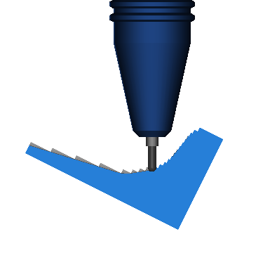
It looks like our holder is colliding into the part during the finishing operation. On a 3-axis machine, our solution might include using a longer tool, but in this case, we have a 5-axis machine – so let’s utilize our machine’s 5-axis simultaneous capabilities to correct this collision!
- Change the tool axis of the finishing operation
by defining a fixed vector
- srf_mill2 properties
- finishing operation
- 5-axis tab
- Select ‘Fixed’ and enter (-0.5,0,1) as the new tool vector
- Run a Machine Simulation

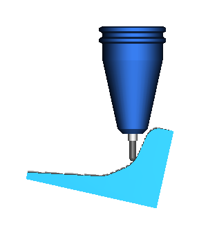
Now we can see that the tool axis has changed to reflect our specified ‘fixed’ tool axis vector (depending on the machine, you will see these changes reflected by rotating either the table or the head). This change has completely eliminated the collisions we were experiencing earlier, and this program is safe enough to send to the machine now. However, let’s take a look at some of the other options we have utilize our 5-axis machine’s capabilities when programming surface milling features.
- Change the 5-axis control of the parallel
finishing operation to utilize 0-degree lead and lean angles
- srf_mill2 properties
- finishing operation
- 5-axis tab
- Select ‘Use Lead and Lean’ under the
‘Multi-Axis’ header
- From: Contact Normal
- Lead Angle: 0
- Lean Angle: 0
- Run a Machine Simulation


As we can see, the ‘Lead and Lean’ options allow us to specify a tool-axis angle in reference to the direction of travel at all times – when we are machining a horizontal wall, the tool is completely vertical, and when we are machining a vertical wall, our tool is horizontal because we have indicated a lead and lean angle of zero. These options can help us generate safe, efficient tool path in a lot of situation, but in this situation, it seems that these lead and lean angles have created machine collision where the table has collided with the machine, so in this case, lead and lean angles may not be our best option.
- Set the tool axis back to vertical, and enable
‘Tilt Axis for Gouge Avoidance’
- srf_mill2 properties
- finishing operation
- 5-axis tab
- Vertical (Z)
- Set ‘Tilt Axis for Gouge Avoidance’ to ‘Lead’
- Run a Machine Simulation


As you probably noticed, when enabling the automatic tilting options, we let FeatureCAM recognize when we are about to collide, and only engage our rotational axes when needed to prevent collisions. So in this case specifically, we kept the tool-axis fixed vertically until the holder was about to collide with the part, and then altered the lead angle accordingly.
For this example, let’s stick with this last option, and send our NC Code to the machine.
Step 5: NC Code
With our final simulation run, our NC Code has been generated and is ready to be sent to the machine.
- Select
the Show NC icon
 to open our NC code in the Results window.
 - Select
the Save NC
 icon to save the displayed code.
 - Save the NC code to your desired directory.
Note: This exercise is for educational purposes. The post-processor used in this exercise is a generic post-processor used for training that will likely not work for your machine. Do not attempt to run any code generated in this exercise.


