Introduction: IoT Based Water Level Indicator Using Ultrasonic Sensor


Today we will be working on a Water level indicator whose data can be monitored through a webpage over a local area network. The water level will be detected by using an ultrasonic distance measurement sensor. We have previously built another IoT based tank water level monitoring system using a float sensor, but in this project, we will use an ultrasonic sensor for detecting the level of water.
For making the project more user friendly, we will be integrating it with a local web server through which you can monitor the data from any device connected to the same Wi-Fi as your ESP board.
Step 1: Required Components

For making this project, we will be needing a few basic components.
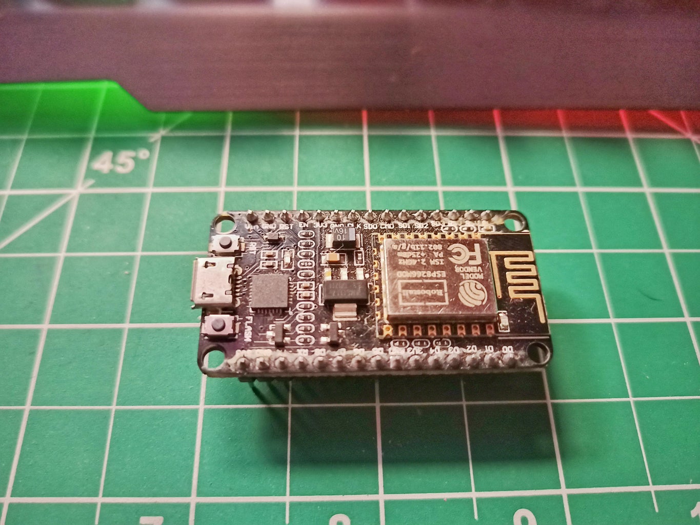
1. ESP8266 NodeMCU board: This will be the heart of our whole project.
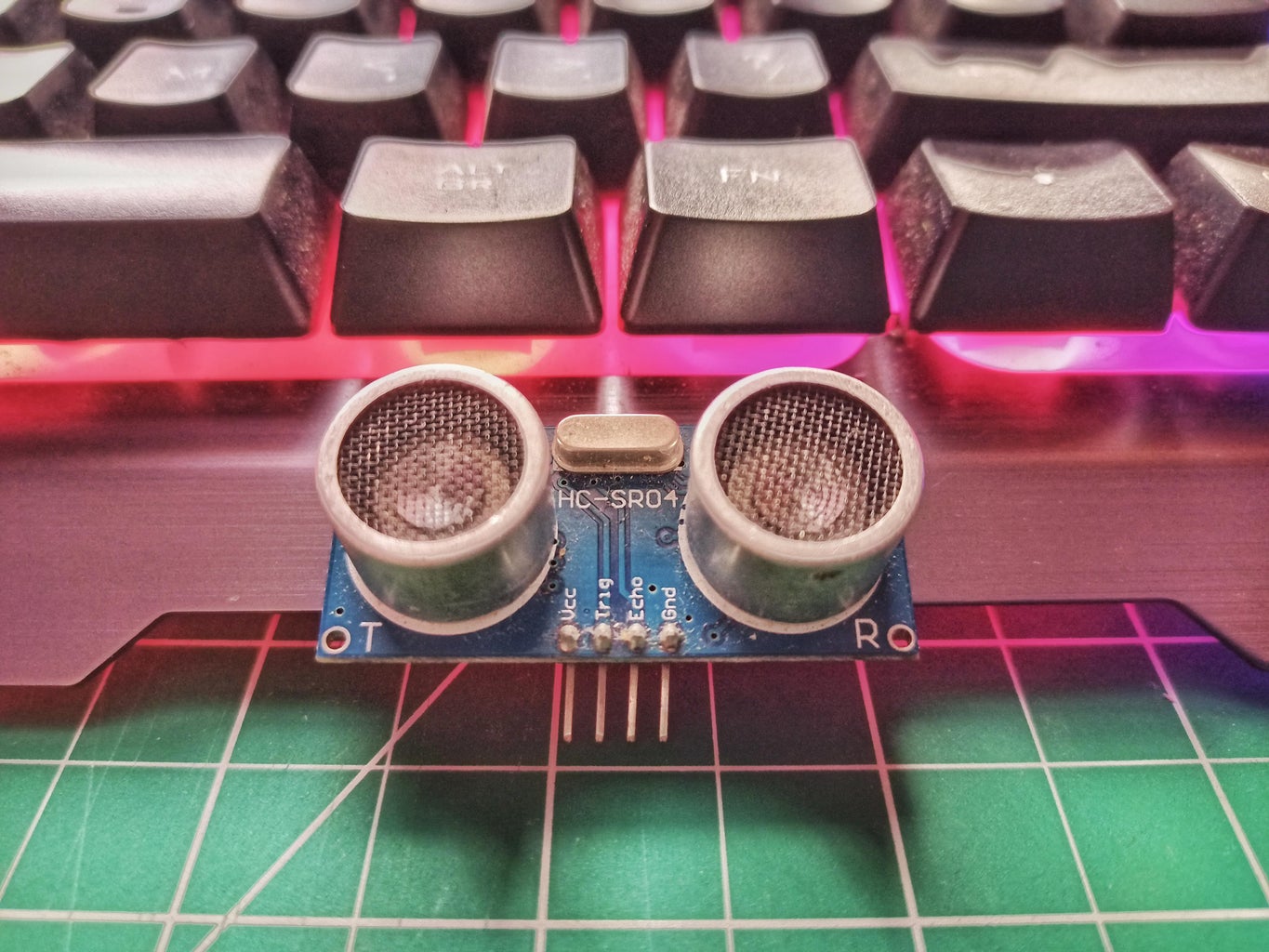
2. HC-SR04 Ultrasonic Sensor: This will be used for sensing the level through ultrasonic sound waves as explained earlier.
3. Breadboard: All the connections will be made on the breadboard itself for making it simple.
4. Jumper wires: As we are using a breadboard, jumper or hookup wires are the way to go for connections.
Step 2: Interfacing Ultrasonic Sensor With NodeMCU


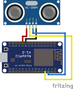
Here is the circuit diagram for the connection.
As we are not using many components, the IoT water level indicator circuit diagram used in this project is fairly simple. We just need to connect the HC-SR04 Ultrasonic sensor to our NodeMCU module. The rest of the work will be done via the software part itself.
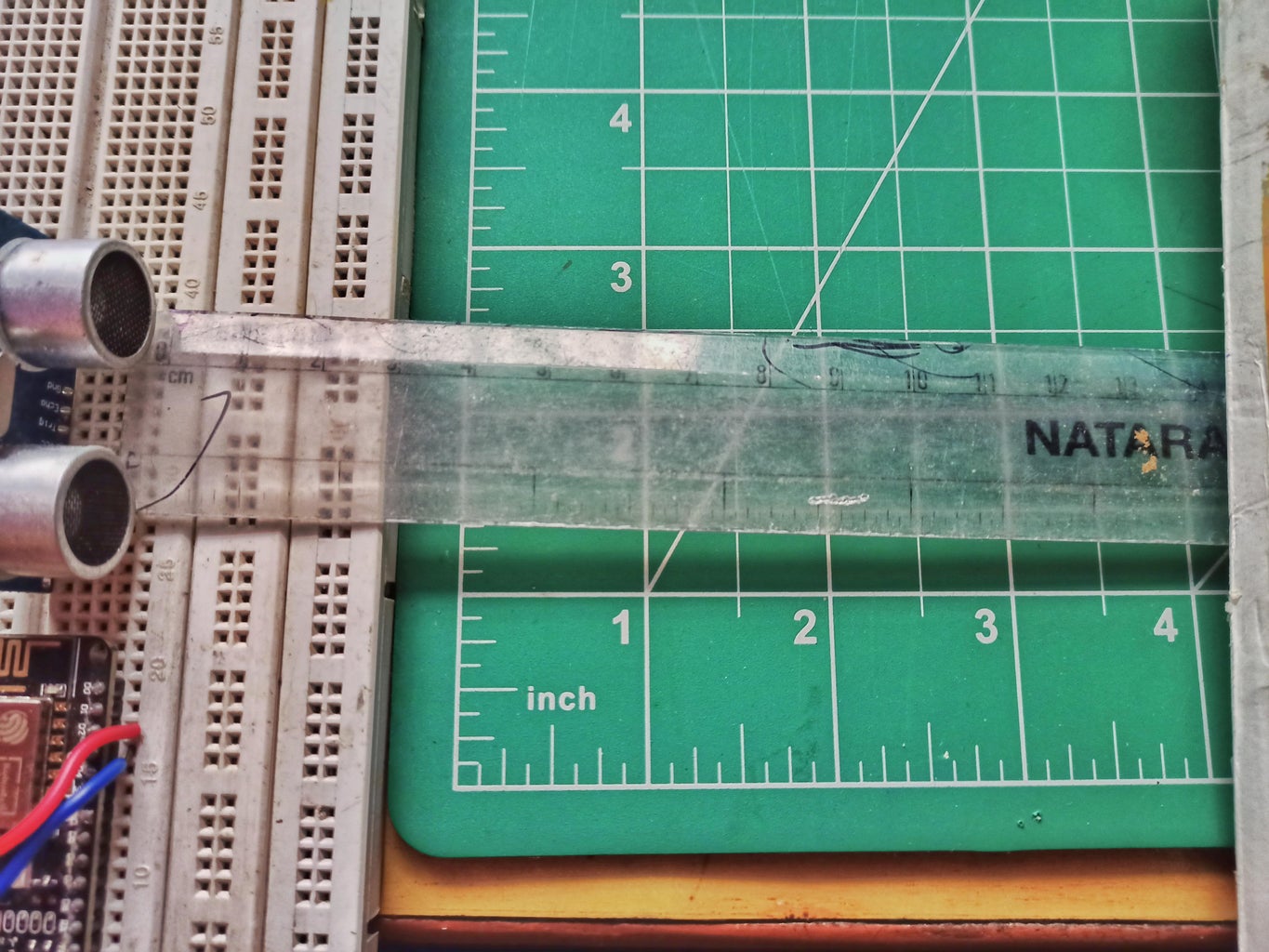
I used a breadboard to connect my ultrasonic sensor with the NodeMCU and then used connecting wires to make the connection. The testing set-up of mine looks like this below, later we will use longer jumper wires to mount the sensor over a demo water tank.
Step 3: Programming NodeMCU to Read Water Level and Display on the Webserver
Now as we have finished making the connections. We will be proceeding to the coding part of the project. Let me clear the algorithm that we will be following while making the code. The complete code can be found at the bottom of this page.
What our Arduino code needs to do is, first of all, connect to the network whose SSID and password are mentioned in the code. After successfully getting it needs to spit out the Local IP address to the serial monitor, so that we may access the webpage created by it. After doing so, it should start dealing with the ultrasonic sensor and after calculating the distance, it must send the data to the webpage that we have created.
Let us understand it part by part, so first of all, we are including the necessary libraries and the global variables that will be used further in the code. Along with that we are also providing the SSID and passwords of our Wi-Fi router and initiating the webserver at port number 80.
#include
#include
#include
int TRIGGER = D3;
int ECHO = D2;
// Replace with your network credentials
const char* ssid = "xxxxx";
const char* password = "xxxxxxx";
ESP8266WebServer server(80); //instantiate server at port 80 (http port)
String page = "";
int data;
Further, in the setup part, we have set the pin mode of the pins as input and output and have stored our page in the page variable using HTML. We have kept a single line HTML code to make up our webpage. In the setup part itself, we get connected to the Wi-Fi router and print IP address to the serial monitor.
The HTML page that we have created refreshes itself every three seconds. You may change it in the code itself.
void setup(void){
pinMode(TRIGGER, OUTPUT);
pinMode(ECHO, INPUT);
delay(1000);
Serial.begin(115200);
WiFi.begin(ssid, password); //begin WiFi connection
Serial.println("");
// Wait for connection
while (WiFi.status() != WL_CONNECTED) {
delay(500);
Serial.print(".");
}
Serial.println("");
Serial.print("Connected to ");
Serial.println(ssid);
Serial.print("IP address: ");
Serial.println(WiFi.localIP());
server.on("/", [](){
page = " Web based Water Level monitor
Current water level is :- "+String(data)+"
";
server.send(200, "text/html", page);
});
server.begin();
Serial.println("Web server started!");
}
Most of the work is done, now in the loop part we just calculate the distance from the ultrasonic sensor and after storing it, we publish the data over our webpage. Our webpage has been made in such a way that, it refreshes every 3 seconds.
void loop(void){
digitalWrite(TRIGGER, LOW);
delayMicroseconds(2);
digitalWrite(TRIGGER, HIGH);
delayMicroseconds(10);
digitalWrite(TRIGGER, LOW);
long duration = pulseIn(ECHO, HIGH);
data = (duration/2) / 29.09;
server.handleClient();
}
This is pretty much it about the code, Now just upload the code, and let us see the project in action.
Step 4: IoT Based Water Level Indicator Testing and Working
You can also check the IoT Based Water Level Indicator working video.
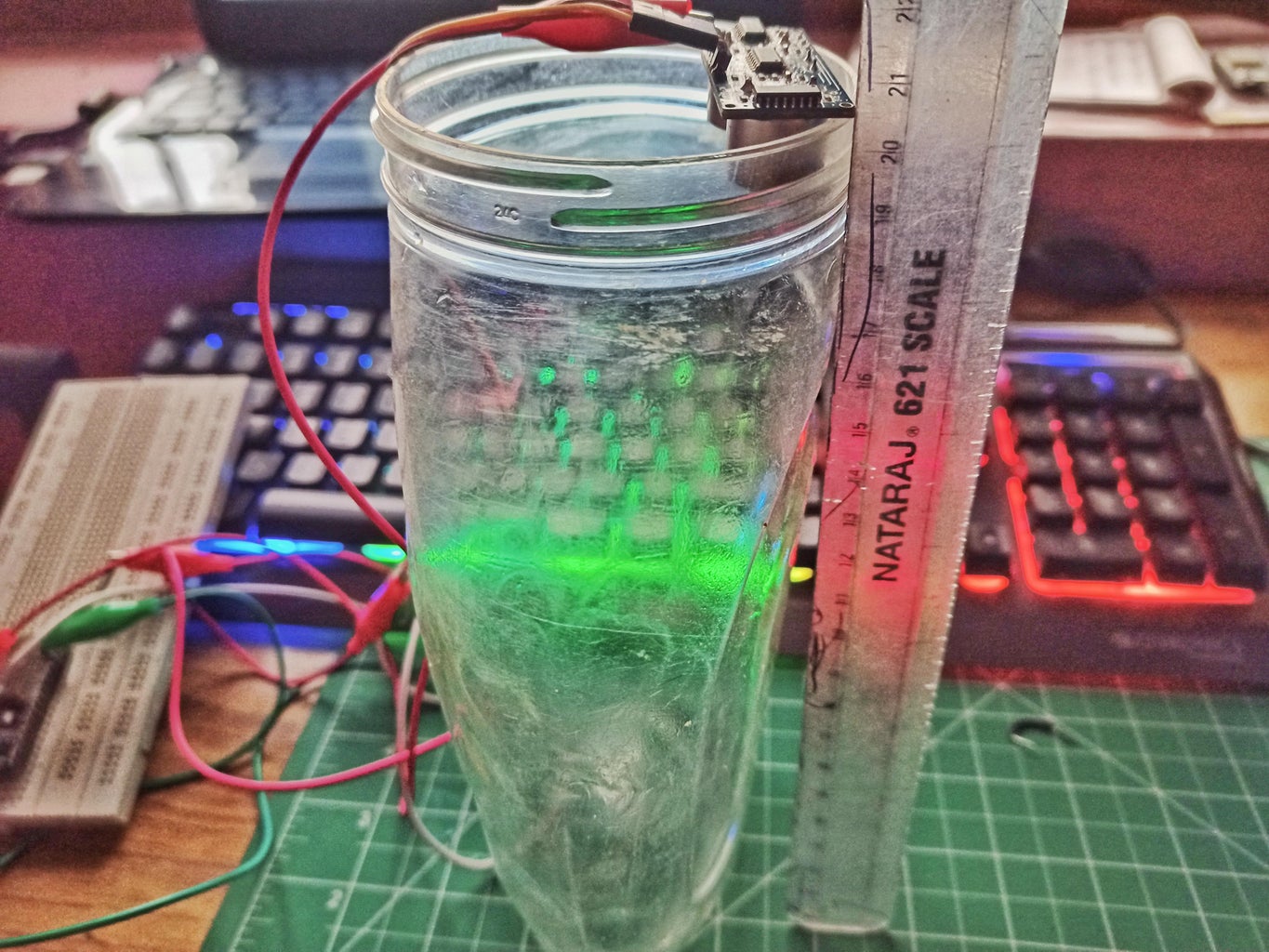
Before directly testing the water level, we tested the distance measurement. After testing this, we set up a water level apparatus for demonstrating the working. We affixed the ultrasonic sensor on top of the jar and also placed a ruler for scale. This way, the monitor will show the data of how empty the jar is in CMs.
I hope you enjoyed the tutorial and learned something useful. If you want to learn more about such interesting projects, then follow us, and also you can visit our website iotdesignpro.com for such interesting content.


