Introduction: Kitchen Guard (a $3 Gas Leakage Detector)


Hi Friends! Welcome to my 50th Instructable.
According to a survey by Titas, the main gas transmission authority in Bangladesh, at least 3,819 gas leak-related accidents occurred in 2013-14, which increased to 5,123 in 2014-15 and still increasing. That means an accident due to gas leakage occurs in every two hours. Proper detection and safety measures can easily prevent such incidents.
Recently I made a simple and cheap gas detection system for detecting the gas leakage. I tried to keep it very simple so that anyone can make a copy of this for his use. Several gas detectors are available in the market but are not affordable for common people.
To keep it simple I didn't use any microcontroller. So it does not require any programming.
So, make one and be safe!
Watch the demo video.
Step 1: Components Required


1. MQ2 Gas Sensor: Gas Sensor(MQ2) module is useful for gas leakage detection (in home and industry). It is suitable for detecting H2, LPG, CH4, CO, Alcohol, Smoke or Propane. Due to its high sensitivity and fast response time, measurement can be taken as soon as possible. The sensitivity of the sensor can be adjusted by the potentiometer. ( buy from ebay.com at $1.28)
2. 5V, 500mA AC wall Adapter: You can use Android Smartphone charger circuit for this purpose.
3. Two 5mm LED (one red, one green)
4. One general purpose PNP transistor (P2N2222A or 2N3906 or BC557)
5. One piezo buzzer
6. 1X100R, 2X1K and 1X4.7K Resistor
Tools Required:
1. Soldering Iron and Solder ( buy one from gearbest.com)
2. Access to a 3D printer (you can buy a low budget 3D printer from here)
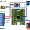
Step 2: Schematic


I used a very few and very common components for the project so that everyone can make one. He/She will be required basic soldering skill. No microcontroller was used, so no programming is required. Grove MQ2 sensor module was used which can measure or detect LPG, Alcohol, Propane, Hydrogen, CO and methane. The module has four pins. Two pin is for providing power to the module and typical voltage rating is 5V. It has two output pins. One gives analog output and another one gives digital output when gas content on the air exceeds a certain threshold. The threshold level can be adjusted by rotating the trimmer pot. The range of concentration it can detect is 100ppm to 10000ppm.
Normally, in a moderately sized closed room, around 700-800ppm [parts per million] gas in the air is considered to be dangerous and the sensor works in this range.
The digital output pin of the sensor goes low when it detects any mentioned gas. For normal condition the output of the pin is high. We want to drive a buzzer when it detects any gas and as the output is low in such a condition, we need a PNP transistor for switching. The emitter pin of the transistor is directly connected to the 5V source. The base is connected to the output pin through a 4.7K resistor. The buzzer is connected to the collector pin of the transistor through a 100R resistor. This resistor is for protecting the buzzer from overcurrent. I also connected a red LED parallelly to the buzzer for indication purpose. A green LED is connected to the power source as a power indicator.
For powering the circuit I used the circuit from an Android charger. 500mA capacity is enough for this purpose. A low price wall adapter will work well.
Step 3: Soldering


I soldered the component in a perf board directly without the sensor. The sensor is connected to the jumper wires. A medium size buzzer was used which can generate about 80dB and enough for drawing concentration even in moderate noise. It will continuously produce sound until the gas concentration goes to the tolerable limit.
The cover of the charger circuit was removed and the circuit is directly soldered to the PCB board. Two long wires are connected to the input side of the charger circuit for connecting it to the AC socket.
All resistors are of quarter watt and the value of the resistor connected to the LEDs are of 1K.
Are you new in soldering? Read the following tutorials.
Step 4: 3D Printing


The circuit needs a case. Is not is? 3D printing can be a very good option for this purpose. I found a good an appropriate design in Thingiverse.com. Thanks to Mr. Johann Wyss for his effort. You can find his design in thingiverse.com.
I used his design with a very small modification. I just make a hole in the top part for an extra LED for power indication. You can download the required stl file from here or the original link provided before.
Are you new in 3D printing? Want to know more about 3D printing? You can read the following link:
https://3dprinting.com/what-is-3d-printing/.
You can join instructable's BEGINNER 3D PRINTING CLASS.
3D printing is amazing. Would you like to buy a 3D printer? Is budget is a fact for you?
Don't worry. You can buy a Desktop 3D Printer only at $150 from here. The printer is available in kit format so you can also get the pleasure of building a 3D printer by yourself from it. Confuse about the quality of such low price printer? I am using this printer more than a year and I am satisfied with it.


Step 5: Assembling


The top part of the 3D design has one hole. I made an extra hole for placing one LED. So, I placed two LEDs in the top cap of the case. Red LED is for alarm indication and Green LED is for power indication. Each LED is connected with a 1K current limiting resistor. After placing the LEDs into the case I added some hot glue for fixing these onto the case. Then I connected the LEDs to the PCB board through 10cm long wires. Hot glue is also used for fixing charger circuit and MQ2 sensor to the PCB board. Then I bring out two wires outside of the case from the input of the charger so that it can be connected to the external supply.

Participated in the
Safe and Secure Challenge


