

Introduction: Lever Arm System


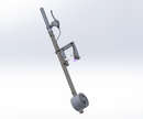
Lever Arm System
Step 1: Lever Arm

Step 2: History Tree for Lever Arm

Step 3: History Tree for Lever Arm

Step 4:

Create a sketch on the front plane, and draw a circle with diameter 25.5mm
Step 5:

Extrude out the base sketch to 302mm.[Boss-Extrude1]
Create a new sketch on the top of the extruded circle, and use convert entities to create the same shape as the base sketch. Extrude it to 152mm [Boss-Extrude2]
Create a new sketch at the bottom of the extruded circle, and use convert entities to get the same shape.Then extrude it to 130mm. [Boss-Extrude3]
On the front plane of the extruded circle, create a new sketch and draw two circles with diameter 8 mm. The distance between their origins is 116 mm. The center point of the circle from the edge is 15mm. Please see the image.
Step 6:

Extrude cut above sketch, cutting them to 20 mm in both direction. [Cut-Extrude4]
Create a circle on the front plane, diameter 17.78 mm. In addition, create a centerline the is tangent to the left arc of the circle. Set the distance from the origin and the centerline to be 302mm.
Step 7:

Extrude cut the circle to 15.2 mm.[Cut-Extrude 1]
Create a new circle at front, diameter 8 mm.
Step 8:

Extrude cut the circle created above to 20mm.[Cut-Extrude2]
Create a new sketch on top, and draw a circle diameter 21.18mm, centered at the origin.
Step 9:

Finally, extrude cut the sketch to 734 mm. [Cut-Extrude3]
Then, you will get the resulting part.
Step 10: Ball Bearing Ring

Step 11: History Tree for Ball Bearing Ring

Step 12:

Create a new sketch on the front plane, and draw two concentric circles.( One is 26.5 mm and another is 35mm)
Step 13:

Extrude out the base sketch to 34 mm.[Boss-Extrude1]
Create a new sketch on top of the extruded circle, and draw two circles.(One diameter is 12.5 mm, and another is 32 mm). Then extrude the region to 4mm. [Boss-Extrude2]
Step 14:

Extrude cut the same sketch of the outer region to 6mm. [Cut-Extrude1]
Step 15:

Create a new sketch at the bottom, and draw a circle with diameter 93mm,centered at the origin. Then Extrude out to 6 mm. [Boss-Extrude 3]
Step 16:

Create another new sketch at the same place above. Draw a circle with diameter 80 mm. Then use convert entity , covering the 26.5 circle into this surface.
Step 17:

Extrude cut the region converting region to 10mm. [Cut-Extrude 2]
Create a new sketch at the largest circle (80mm), and draw a circle with diameter 26 mm. Use Extrude cut the sketch region to 5mm [Boss-Extrude 9]
Step 18:

Create another circle at top diameter 22.5 mm. Extrude cut to 5mm. [Cut-Extrude3]
Step 19:

The resulting part.
Step 20: Lever Arm Ring

Step 21: History Tree for Lever Arm Ring

Step 22:

Create a sketch on the front plane, and draw two circles, centered at the origin.(One with diameter 81.5mm ,another is 101.25mm)
Step 23:

Extrude out the sketch region to 21 mm. [Boss-Extrude1]
Step 24:

Create a new sketch on the front plane, and draw a circle with diameter 94 mm. Then extrude out to 50 mm. [Boss-Extrude2]
Step 25:

Create a new sketch on the top plane, and draw a circle with diameter 25.4. Create two construction lines to define its location.
Step 26:

Cutting through the sketch region using Extrude Cut. [Cut-Extrude1]
Create a new sketch on the front plane, and draw two circles, centered at the origin.(One with diameter 95mm, another is 37mm).
Finally, extrude out the sketch plane to 2.5mm.[Boss-Extrude3]
Step 27:

The resulting part.
Step 28: Ball Bearing Fastener

Step 29: History Tree for Ball Bearing Fastener

Step 30:

Create a new sketch on the front plane, and draw two circles, centered at the origin. (One with diameter 77mm, and another with diameter 35.5 mm)
Step 31:

Extrude out the base sketch to 4.3mm [ Boss-Extrude_whole]
Step 32:

The resulting part.
Step 33: Wheel Fastener

Step 34: History Tree for Wheel Fastener

Step 35:

Create a new sketch on the front plane, and draw two concentric circles, centered at the origin. (Larger one with diameter 23 mm, and smaller one with diameter 13mm)
Step 36:

Extrude out to 18.5 mm.[Boss-Extrude1]
Create a new sketch at top of the extruded circle, and draw a circle with diameter 13mm, centered at the origin. Extrude cut the circle to 30 mm. [ Cut-Extrude1]
Step 37:

The resulting part.
Step 38: Lever Arm System Assembly

Step 39: History Tree of Lever Arm System Assembly

Step 40: History Tree of Lever Arm System Assembly

Step 41:

Insert the parts into a new assembly. ( Lever arm ring, Ball bearing ring , two socket head cap screw [part number: 93235A355 in Master Carr], BallBearing[part number: 5972K503 in Master Carr, Lever arm, adaptor, Stainless steel nut[part number:94777A102 in Master Carr] , Handle Adaptor)
Create a coincident mate between lever arm’s face and ball bearing’s face.[Coincident8]
Step 42:

Create a concentric mate between the edge of lever arm ring and the edge of ballbearing ring. [Concentric7]
Step 43:

Create a parallel mate between the front plane of lever arm ring and the front plane of Ballbearing ring. [Parallel9]
Step 44:

Create a concentric mate between the face of Ballbearing ring and the face of Ballbearing, and select the lock rotation. [Concentric 1]
Step 45:

Create a coincident mate between the face of lever arm ring and the face of ball bearing. [Coincident 1]
Step 46:

Create a concentric mate between lever arm ring and the lever arm, so that the lever arm can go through the lever arm ring, and locking the rotation.[Concentric 2]
Step 47:

Create a concentric mate between the screw and the lever arm’s hole, and lock the rotation, [Concentric 3]
Step 48:

Create a tangent mate between the socket screw and the lever arm. [ Tangent1]
Step 49:

Repeat step 8 and step 9, creating concentric mate and tangent mate between the screw and the lever arm’s hole. [Concentric 7 & Tangent 3]
Step 50:

Create a concentric mate between edges of lever arm and the edges adapter. [Concentric 9]
Step 51:

Create a concentric mate between screw and the nut and then lock rotation. [Concentric 12]
Step 52:

Create a tangent mate between the lever arm and the nut. [Tangent 15]
Step 53:

Repeat the step 12 and step 12, creating a concentric mate and tangent mate between the screw and the lever arm’s hole. [Concentric 13 & Tangent 16]
Step 54:

Create a tangent mate between the face of lever arm ring and the edge nut. [Tangent 17]
Step 55:

Select reference geometry, and click Axis. Create a coincident mate between the axis of the lever arm and the axis of adapter. [Coincident 6]
Step 56:

Create three Concentric mates between lever arm and handle adaptor. [Concentric 14 & Concentric 15&Concentric 17]
Step 57:

The resulting assembly.
