Introduction: Lights Out Night Light
It's time for bed. You get up to turn off the lights for the night, and after you flip the switch, you realize you have the pitch black journey back to the safety of your bed ahead of you. Lucky for you, night lights were invented, and you've come to the right place to find one! But... how you can fall asleep when that pesky night light is on through the night illuminating your room? In addition, aren't you tired of this empty darkness causing your night lights to remain on and waste energy? Well, you are STILL in the right place, because we have exactly what you need!
We want to brighten your life by helping you make a sustainable night light.
In this tutorial, we are going to walk you through the process of building a night light that will turn off with a timer. The system will be able to recognize when the main light is turned off, via a light sensor, and turn on the light for a user-set time, and turn off after that time elapses. This night light is different than other night lights because it waste energy by remaining on when you are asleep and don't need it. This project uses two types of boards, Basys 3 and Arduino, and a light sensor.
Creators: Luke McDaniel, Erik Ramazzini, Monica Negrete, Hayley Young
Step 1: Materials and Software


Materials
- Basys 3 Artix-7 FPGA Trainer Board
https://store.digilentinc.com/basys-3-artix-7-fpga...
- Arduino Uno Rev3
https://store.arduino.cc/usa/arduino-uno-rev3
- Breadboard
https://www.amazon.com/Elegoo-EL-CK-002-Electronic...
- 10k Ω Resistor
Same link as breadboard
- Jumper Wires
Same link as breadboard
- Light Sensor (Mini Photocell)
https://www.sparkfun.com/products/9088
Software
- Vivado HL WebPACK Edition (Attached PDF includes instructions)
https://www.xilinx.com/products/design-tools/vivad...
- Arduino IDE

Step 2: System Architecture


The next step is to understand the system architecture. We created a black box diagram and a finite state machine (displayed above) in order to organize the structure of our design before getting into the logistics.
Overall Design
Inputs
- Light Sensor: determines amount of light in the room
Outputs
Anodes: determines which 7-segment displays will be used
Segments: displays the timer
LED: displays night light conditions of ON or OFF
Arduino
Input
- Light sensor signal: analog value of amount of light in the room
Output
- Light Input (1 bit): signal that determines the room's light condition
Basys 3
Input
- Light Input (1 bit): signal that determines the room's light condition
- Switches
- CLK
Output
- Anodes: determines which 7-segment displays will be used
- Segments: displays the timer
- LED: displays night light conditions of ON or OFF
Step 3: Hardware and Arduino Code


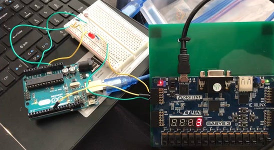
Hardware
In order to understand the Arduino code, we must understand the hardware the code is interacting with. The circuit on our breadboard includes a photocell, a light emitting diode, and multiple wires and resistors to complete it. The circuit starts by sending power to the photocell, which then reads the amount of light surrounding it. This information is transferred to the analog pin, A0, which makes it readable for the Basys board. The Basys board then takes this information, starts counting, and sends a signal for the LED to turn on.
Arduino Code
The Arduino code itself communicates with the Basys board by sending it a signal when the light surrounding the device is darker than a specified threshold. This signal triggered by a dark room with lead to the LED will turn on. We found through experiment that the average threshold for our specific photocell in dark rooms is 30 - 60. Every photocell has a different amount of sensitivity, so other photocells may have different thresholds. In our published code, we made the threshold 100 for demonstration purposes.


