Introduction: Location Reporting Clock
This instructable was created in fulfillment of the project requirement of the Makecourse at the University of South Florida (www.makecourse.com)
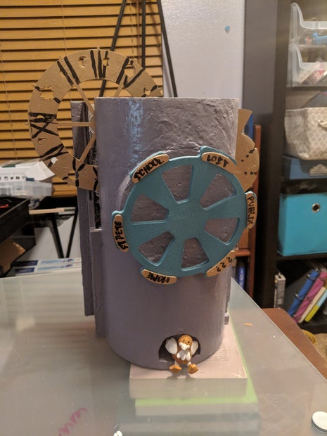
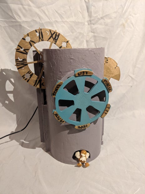
Introducing a clock for the perpetually misplaced and habitually late. Partially inspired by the location tracking clock the Weasley family owns in Harry Potter - I wanted to make a simple location "reporting/tracking" clock with an interesting design.
This project uses an Arduino Uno integrated with Keuwlsoft's Bluetooth Electronics Android app to let you set your intended destination before you leave your house, so whoever's still at home can see where you (probably) wandered off to. It keeps track of the time, as well, if (much like its creator) your answer to "What time is it?" is normally something like "Well... it's about 2:45ish, I suppose."
Step 1: Materials and Tools
Parts and Materials List
Hardware
| # | Part | Source |
|---|---|---|
| 1x | Arduino Uno Microcontroller | |
| 2x | Adafruit Motor Shield V2.3 + included headers | |
| 1x | HC-05 Bluetooth module | |
| 3x | Nema-17 bipolar stepper motor (200 step/rev, 12V) | |
| 1x | Power supply (12V) | - |
| 1x | Short breadboard | |
| 1x | Plastic electronics enclosure box | |
| -- | Assorted male-male wires | - |
| 1x | 4.7k ohm resistor | |
| 1x | 2.2k ohm resistor | - |
| 2x | 8-pin stackable header | |
| 1x | 6-pin stackable header | - |
| 1x | 10-pin stackable header | - |
Materials
| # | Part | Source |
|---|---|---|
| 1x | 1 kg 1.75mm spool PLA for 3D printing | |
| -- | Solder | - |
| -- | Assorted grit sand paper/ sanding blocks | - |
| 1x | Bondo | - |
| 1x | Spray primer (matte gray or white) | - |
| 2-3x | Spray paint (each a different color) | - |
| -- | Small tube acrylic hobby paint | - |
| 2x | 2 oz. Oven bake-able modelling clay (different colors) (optional) |
Tools
| Part |
|---|
| 3D printer |
| Soldering iron |
| Small electronics screw driver set |
| Dremel + cutting bit |
| Set of files |
Additional Tools (may be necessary)
| Part |
|---|
| Needlenose pliers |
| Wire cutters |
| Wire stripper |
Step 2: Modelling and Physical Design
Parts
3D Printed Parts
| Part |
|---|
| Base |
| Location dial |
| Hour dial |
| Minute dial |
| Location name plates (x6) |
Optional Parts
| Part |
|---|
| Figure to sit in the "front door" |
Assembly
1) Base
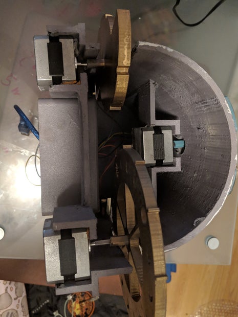
This is the main exterior of the print. It can be whatever shape you'd like - I went for a simple round tower with an opening in the front to leave open the option to add a cuckoo clock spring feature in the future (as of the current version, there's just a little bird figure sitting in the opening).
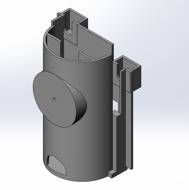
For this version, the base is 300mm tall and about 180mm wide at it's widest point.
Key points for designing your own:
- The base should be long and wide enough to fit two rows of motors with room for the hour and minute dials to slot inside.
- The inside of mine is left hollow so more features can be added later and to save on print time
- The electronics will be housed in a plastic enclosure recessed into the back, which dictates the minimum height the motors can be placed at, depending on how you want to orient the enclosure
2) Location dial and location name plates
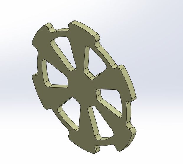
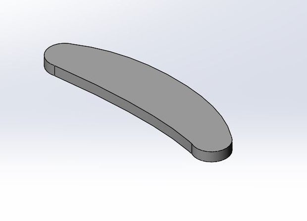
The .stl provided and the subsequent code provided in the programming step are for a dial with 6 options, but the code can be modified if you choose to design yours with a different number. For the version shown, the locations are painted on individual name plates that are attached to each spot so they can be changed out.
Key points for designing your own:
- This is the front dial, so size the overall radius accordingly - it should be large enough to read your locations
- Each location spot should be spaced at equal angles around the center
- You can either design the location text into the dial, or leave them blank so they can be switched out down the line
- Connecting the dial to the motor:
- Option 1: A hollow shaft on the back to slide over the motor shaft, such as in this design
- Option 2: A solid shaft that attaches with shaft collars
- If you choose this option, make sure the center hole in the base is wide enough to accommodate
3) Hour dial
The hour dial has 12 teeth, one positioned for the top of each hour.
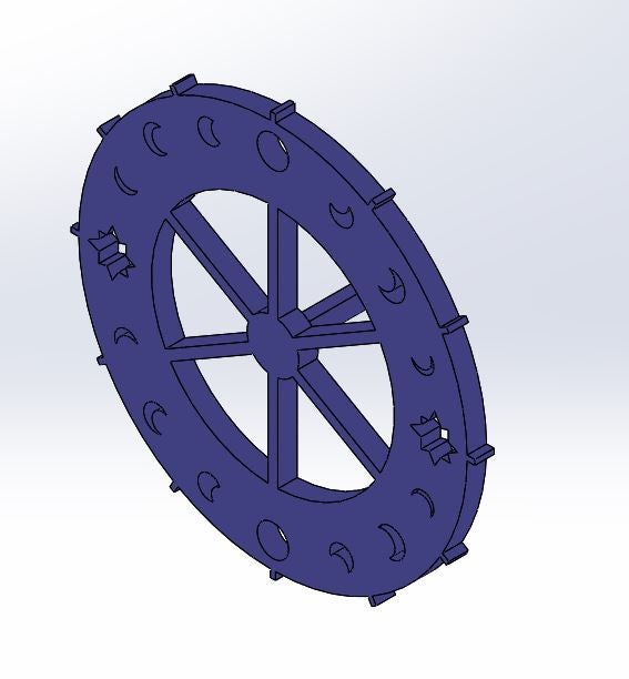
4) Minute dial
For this particular design, I decided to go with a dial that completes one full rotation every two hours. The circular face narrows starting at the top of the hour (hour 1 - minute zero) until it reaches the end of the hour (minute 59) over 180 degrees, then spikes back up to the widest point again at the next minute zero (hour 2 - minute zero), with marks at the 15, 30 and 45 minute points.
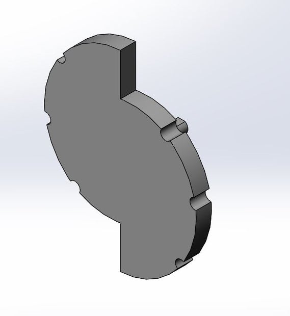
Key points for designing your own:
- The dial can be designed like the hour dial above to give a more accurate reading, or slightly less readable like the one provided
- Additional size constraints for designing the hour/minute dials: if the two back motors are mounted on the same place:
- i) If the dial faces will be sitting on the same plane, the radii will need to be small enough to allow them to move freely next to each other, and the shafts attached to the motor will be the same length
- ii) If the faces will be off set, there's more room in size variation, but the shafts will need to be different lengths
5) Figure (Optional)
For this project, I just modelled a little bird out of some sculpey modelling clay and baked it per the package instructions (225 degrees fahrenheit for 15 minutes per 1/2 inch of thickness).
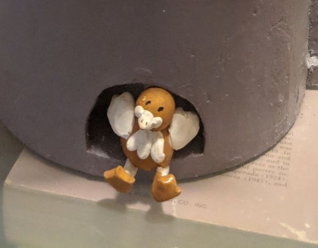
If you don't want to go the clay route, you can either 3D model or find a cute print off thingiverse to suite your needs.
Step 3: Motor Shield Set Up
Before you assemble everything, you'll want to make sure all your electronics and code are working smoothly while you can easily pull things apart. We'll start with the motor shields:
Parts and Materials
| # | Part |
|---|---|
| 1x | Arduino Uno microcontroller |
| 2x | Adafruit Motor Shield V2.3 + included headers |
| 2x | 8-pin stackable header |
| 1x | 6-pin stackable header |
| 1x | 10-pin stackable header |
| -- | Soldering iron |
| -- | Solder |
Steps
The first thing you'll need to do is connect the headers to the motor shields and solder
- First motor shield headers (bottom shield) - stackable headers:
- Fit a stackable header with appropriate number pins in each of the four sections noted below through the top of the motor shield (these will connect to the arduino below and the additional shield stacked above)
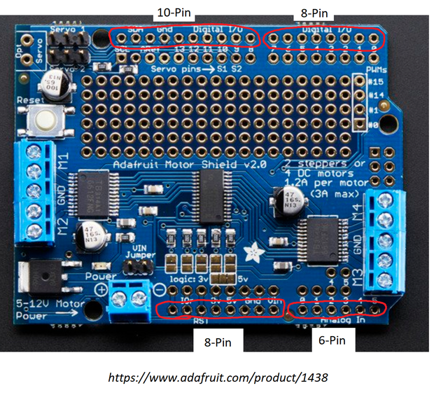
- Flip the motor shield over so it's resting on the pins, front side facing down
- Solder one pin from each header to hold them in place, then go back and solder the rest of the pins
- Fit a stackable header with appropriate number pins in each of the four sections noted below through the top of the motor shield (these will connect to the arduino below and the additional shield stacked above)
- First motor shield - jumper
- Solder the right most jumper as pictured below

- Solder the right most jumper as pictured below
- Second motor shield (top shield) - use headers included with kit
- This time using the pins provided with the motor shield, solder as you did with the previous motor shield
- Second motor shield - jumper
- Leave all jumpers unsoldered; this shield will use the default address
Step 4: Wiring
Parts and Materials
| # | Part |
|---|---|
| 1x | Arduino Uno microcontroller |
| 2x | Adafruit Motor Shield V2.3 |
| 1x | HC-05 Bluetooth module |
| 3x | Nema-17 bipolar stepper motor (200 step/rev, 12V) |
| -- | USB 2.0 to 3.0 cable |
| -- | Breadboard |
| -- | Assorted male-male wires |
| 1x | 4.7k ohm resistor |
| 1x | 2.2k ohm resistor |
| -- | Screwdriver with small flat head |
Steps
- First hook up one of the motors to the M1/M2 terminals of the motor shield with the soldered jumper, as in the photo below:

*Note the wire order: red, yellow, gray, green*
Use the flat head screw driver to loosen/tighten the screw clamps
- Next, hook up the remaining two motors to the other motor shield in the same manner, one on the M1/M2 terminals and the other on the M3/M4 terminals
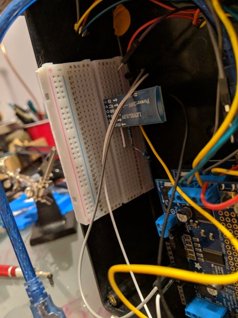
- Now wire the HC-05 bluetooth module to the bread board, and wire the breadboard to the motor shield with the two motors attached:

- Wire the positive rail of the breadboard to the 5V pin of the motor shield, and the negative rail to the ground pin of the motor shield
- Place the 2.2k ohm and 4.7k ohm resistors in series on the breadboard
- Insert the bluetooth module into the breadboard and wire the following connections:
- VCC pin to the positive rail of the breadboard
- GND pin to the negative rail of the breadboard
- TXD pin to pin 0 (RX pin) of the motor shield
- RXD pin to the junction where the 2 resistors meet
- Connect the end of one of the resistors to the negative rail of the breadboard
- Connect the end of the other resistor to pin 1 (TX pin) of the motor shield
- Attach the motor shields to the arduino:
- Fit the pins on the bottom of the motor shield with the single motor attached into the headers of the arduino board and gently press until the pins are seated
- Fit the pins on the bottom of the other motor shield into the the headers of the motor shield now attached to the arduino
Step 5: Programming
The code for this project was done using the Arduino IDE. The full sketch is available for download.
Overview
Dials
The front dial is set to turn clockwise back to the home location, and then turn from there to which ever location was chosen.
The minute dial turns one half of a full rotation per hour, and it moves forward 5 steps every 3 minutes. The hour dial turns one full rotation over the course of 12 hours, and it moves forward 5 steps approximately every 18 minutes. The time is kept synced to the actual time passing by tracking the milliseconds that have passed through the milli() function.
Bluetooth integration
The Arduino receives command data through the serial connection between the bluetooth module and the Arduino. Then, Keuwlsoft's Bluetooth Electronics app is able to connect to the HC-05 bluetooth module attached to the board. In the location tracking section of the Arduino sketch's void loop, the characters that can be received via the app are each assigned a function. A-F are assigned to move the location dial, and G-J reset the time.
- Location (A-F):
- Each time a character is received, the dial turns back to the home location
- Set this location by moving the dial to the desired home position each time the project is turned on
- Then the dial will move the necessary number of steps to reach the location the app user requested
- Each time a character is received, the dial turns back to the home location
- Resetting time (G-J):
- When the pause button is pressed, the motors for the time dials stop moving
- The user must then turn the hour and minute dial so the clock reads 12:00
- Integers can then be entered into the bluetooth app and sent to the arduino
- When the resume button is pressed, the motors turn to the entered time and resume regular function
- Since the user might enter a time in between "periods" for the dials to turn, code has been added to calculate this partial period (the remainder variables in the sketch), turn when the number of milliseconds has elapsed, and then resume regular function
Full details of the bluetooth app will be outlined in the next step.
Code
/////////////////////////////////////// ///////Location Tracking Clock///////////////////////////////////////////////include the following libraries#include #include #include "utility\Adafruit_MS_PWMServoDriver.h"//initialze motor shieldsAdafruit_MotorShield AFMSbot(0x61); // bottom shield, 0x61 jumper solderedAdafruit_MotorShield AFMStop(0x60); // top shield, default address, no jumpers//initialize stepper motors on shieldsAdafruit_StepperMotor *stepperLoc = AFMSbot.getStepper(200, 1); //location stepperAdafruit_StepperMotor *stepperMin = AFMStop.getStepper(200, 1); //minute hand stepperAdafruit_StepperMotor *stepperHour = AFMStop.getStepper(200, 2); //hour hand stepper char BluetoothData; //Bluetooth data received //variables to hold/ track bluetooth location statesint currLoc = 0; //# of steps from home int homeLoc = 0; //# of steps back to home //variables to track time during normal clock movementint minPeriod = 180000; //ms bw minute hand movement /* Calculation: (36000 ms/step)*(100 total steps)* (5 steps/period) = 180000 steps per period */int hourPeriod = 1080000; //ms bw hour hand movement /* Calculation: (4320000 ms/12hr)*(216000 ms/step)*(5 steps/period)=1080000 steps per period */long minNow = 0; // current minute (20 total steps)long hourNow = 0; //current hour (40 total steps)//variables to set user input timeint changeTime = 0; // 0=regular time, 1=change timeint setTime = 0; // 0=regular movement, 1= pause clock movementint userHour = 0; //user input hour from bluetooth appint userMin = 0; //user input minutes from bluetooth applong newHourMilli = 0; //user input time in mslong newMinMilli = 0; //user input minutes in msint newHourPeriod; //# of hour dial periods to set timeint newMinPeriod; //# of minute dial periods to set timelong hourRem; //ms to wait before resuming hour dial motionlong minRem; //ms to wait before resuming minute dial motionvoid setup() { Serial.begin(9600); //begin serial communication AFMStop.begin(); //start the top shield AFMSbot.begin(); //start bottom shield//set motor speeds stepperLoc->setSpeed(5); //5 rpm stepperHour->setSpeed(5); //5 rpm stepperMin->setSpeed(5); //5 rpm }void loop() {//////////////////////Clock dial movement (hours/minutes) and time set/////////////////// if (changeTime == 0){ //default state if(millis() > minNow + minPeriod){ //Check until millis reaches next marked period for minute dial minNow=millis(); //replace with new current minute state stepperMin->step(5,FORWARD,SINGLE); //move minute dial forward } if (millis() > hourNow + hourPeriod){ //Check until millis reaches next marked period for hour dial hourNow = millis(); //replace with new current hour state stepperHour->step(5,BACKWARD,SINGLE); //move hour dial forward } } if(changeTime==1){ //pause normal clock movement //read user entered hour/minute to set time and match up with code dictated periods if(setTime==1){ newMinMilli = long(userMin)*60*1000; //calculate hour milliseconds from user input newHourMilli = long(userHour)*60*60*1000 + newMinMilli; //calculate overall ms based on user time input newMinPeriod = int(newMinMilli/minPeriod)*5; //steps to move beyond zero minute point newHourPeriod = int(newHourMilli/hourPeriod)*5; //steps to move beyong zero hour point hourRem = (newHourMilli % hourPeriod)*hourPeriod; //calculate remaining ms to wait before next addtional move of hour dial minRem = (newMinMilli % minPeriod)*minPeriod; //calculate remaining ms to wait before next additional move of minute dial } if(newMinMilli != 0 && newHourMilli != 0){ newHourPeriod = int(newHourMilli / 1080000)*5; //move to new hour newMinPeriod = int(newMinMilli / 180000)*5; //move to new minute stepperHour->step(newHourPeriod,BACKWARD,SINGLE); stepperMin->step(newMinPeriod,FORWARD,SINGLE); if (millis()>millis()+hourRem){ //wait hour ms remainder before moving to next hour period stepperHour->step(5,BACKWARD,SINGLE); } if (millis()>millis()+minRem){ //wait minute ms remainder before moving to next minute period stepperMin->step(5,FORWARD,SINGLE); } //reset variables and resume regular clock movement newMinMilli = 0; newHourMilli = 0; userMin=0; userHour=0; setTime=0; changeTime=0; } } //////////////////////Location tracking and time update via bluetooth app/////////////////// if (Serial.available()){ BluetoothData=Serial.read(); //Get next character from bluetooth ////location tracking - characters A - F if(BluetoothData=='A'){ // Location 1 pressed homeLoc = 200-currLoc; //calculate steps to home dial (location 1) stepperLoc->step(homeLoc, BACKWARD, SINGLE); //move dial to home location currLoc = 0; //set new current location } if(BluetoothData=='B'){ // Location 2 pressed homeLoc = 200-currLoc; //calculate steps to home dial (location 1) stepperLoc->step(homeLoc+34, BACKWARD, SINGLE); //move stepper home then to desired location currLoc = 34; //set new current location } if(BluetoothData=='C'){ // Location 3 pressed homeLoc = 200-currLoc; stepperLoc->step(homeLoc+67, BACKWARD, SINGLE); currLoc = 67; } if(BluetoothData=='D'){ // Location 4 pressed homeLoc = 200-currLoc; stepperLoc->step(homeLoc+100, BACKWARD, SINGLE); currLoc = 100; } if(BluetoothData=='E'){ // Location 5 pressed homeLoc = 200-currLoc; stepperLoc->step(homeLoc+134, BACKWARD, SINGLE); currLoc = 134; } if(BluetoothData=='F'){ // Location 6 pressed homeLoc = 200-currLoc; stepperLoc->step(homeLoc+167, BACKWARD, SINGLE); currLoc = 167; } ////time update G - J if(BluetoothData=='G'){ //pause clock movement changeTime=1; } if(BluetoothData=='H'){ //set time, resume movement setTime=1; } if(BluetoothData=='I'){ //user input - minutes userMin=Serial.parseInt(); } if(BluetoothData=='J'){ //user input - hours userHour=Serial.parseInt(); } }//close void loop() } Attachments
Step 6: Bluetooth Integration
Keuwlsoft's Bluetooth Electronics app can be downloaded from the Google Play store, and will connect to the HC-05 module. Additional information about the base app and its functionality can be found here on their website.
The Bluetooth Electrionics app will let you create panels with controls that will send serial data to the bluetooth module hooked up to the project. For this project, you'll want to create two different panels - one for controlling the location, and one for setting the time.
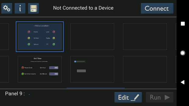
Creating the Panels
Panel One: Location Tracking
- Select a blank panel and touch edit to open up the panel editor
- You'll need six buttons, one for each location on the location dial of the physical project
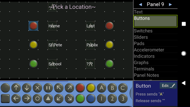
- To place a button: select "Buttons" from the menu on the right, and drag a button from the menu on the bottom onto the panel
- When your buttons are on the panel and arranged, select "Text" from the right-hand menu
- Drag one of the four left-most text box options from the bottom menu to the panel for each of your locations and arrange accordingly
- Select one of the panels text boxes, and use the bottom right menu to edit the label text
- The character each button sends to the Arduino needs to be set:
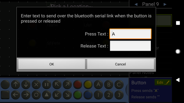
- Assign each location a different character (A-F) in the "Press Text" box; leave the "Release Text" box blank or clear it if there is a character already assigned
Panel Two - Set Time
- Return to the app's main screen and select a new blank panel to edit
- In this panel, add two buttons to the screen and label them - these will be the stop and start clock buttons
- For the stop button, assign 'G' to "Press Text", and nothing to "Release Text"
- For the start/ set new time button, assign 'H' to "Press Text", and nothing to "Release Text"
- Select "Terminals" from the right-hand menu, and from the bottom menu drag two of the top-left send boxes to the screen
- Assign these labels for minute and hour
- For the send box labeled minute, assign 'I' to "Press Text", and nothing to "Release Text"
- For the send box labeled hour, assign 'J' to "Press Text", and nothing to "Release Text"
Your app now has everything it needs to function with the project!
Step 7: Assembly - Part 1 (Part Preparation)
Parts and Materials
3D Printed Parts
| Part |
|---|
| Base |
| Location dial |
| Hour dial |
| Minute dial |
| Location name plates (x6) |
Additional Supplies
| Part |
|---|
| Glue |
| Small picture hanging adhesive strips |
| Bondo |
| Sand paper/ sanding blocks |
| Spray paint primer |
| Spray paint - assorted colors, minimum of 2 |
| Black acrylic paint/small brush |
| Dremel with cutting bits |
| Plastic enclosure |
Steps
First, the 3D printed parts need to prepped and painted.
Prep the Base
- If the base was printed in multiple pieces, assemble the pieces and glue together
- If you're happy with the quality of your print, you can skip further prep
- Start by sanding the base if the print came out particularly rough
- Wipe down with a wet cloth to clear of sanding debris and pat dry with a soft towel
- Apply a thin coat of bondo over the entire base, per instructions on container

- When dry, sand to an even finish
- If you have a sanding bit for the dremel, you can (carefully) use this to quickly sand down any spots that are significantly thicker than others
- Reapply if necessary
- Wipe down with wet cloth when desired smoothness is reached, then pat dry
Prep the Enclosure
- Using the cutting bit of the dremel, cut out a ~2.5 inch slot near one of the short edges in the lid of the enclosure
- In the base of the enclosure, cut three holes where the motor wires will feed through:
- A ~2 inch hole near the top of the main face of the enclosure
- One hole on each of the two adjacent long edges
Prime and Paint
- Prime all printed pieces and the plastic enclosure/ lid with the spray primer
- When dry, use one color of spray paint for the base and the enclosure, and a separate color (or colors) for the dials and plaques. Apply multiple coats if necessary for better coverage.
- Location name plates:
- Use the acrylic paint to write in the locations you chose in your app on the plaques
- Cut the adhesive strips to fit the backs of the plaques and stick the plaques to the location dial
- Use the acrylic paint to apply numbers to the hour dial, and markers for 15/30/45 minutes on the minute dial
Step 8: Assembly - Part 2 (Part Assembly)
Parts and Materials
| Part |
|---|
| Painted parts from previous step |
| 3x Motors (remove from motor shield temporarily if already attached) |
| Tape |
Steps
- Place one of the motors in the front motor bracket, wire edge down, and thread the wires through the bottom opening before fully setting the motor in place
- Slide the location dial shaft over the motor shaft through the hole in the face at the front, making sure it is snug and the motor shaft turns with the dial when spun
- Attach the minute dial and the hour dial to the remaining motors. Slide the minute dial motor into the back right motor bracket, and the hour dial into the back left motor bracket, again threading the wires through the bottom openings
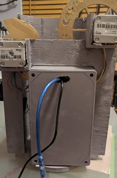
- Place the enclosure up to the back of the project and thread the motor wires through their respective holes
- Tape the wires to the inside of the enclosure for now, and keep track of which set goes to which motor
- Seat the enclosure fully in the base, but do not secure it until the Arduino is fully wired back up and the features are all running
Step 9: Assembly - Part 3 (Electrical Components)
Parts and Materials
| Part |
|---|
| Assembled base |
| Arduino + shields |
| Picture hanging strips |
Steps
- Bring your assembled project to a location that is close enough to hook up to a computer when the Arduino is inside the enclosure.
- Connect the motors to the appropriate motor shield location and make sure the motor shields are seated properly on the Arduino
- The location dial motor connects to M1/M2 on the bottom shield
- The minute dial motor connects to M1/M2 on the top shield
- The hour dial motor connects to M3/M4 on the top shield
- Apply one or two of the adhesive strips to the back of the breadboard and stick it to one of the sides inside the enclosure
- Gently apply one adhesive strip to a blank spot on the back of the Arduino, and stick to the inside of the enclosure
- Turn the location dial so Home is facing upwards (or whatever was set to 'A' in your bluetooth app)
- Plug in the USB cable and upload code
- **Note:** The RX/TX pins need to be disconnected before each upload, or the upload will fail; reconnect when done.
- If your cable is too short to keep comfortably plugged into the computer, either:
- a) Hook up a small USB battery pack after code is uploaded, or,
- b) Connect a power cable to the Arduino's barrel jack and plug into the wall
- Connect to bluetooth:
- Open the Bluetooth Electronics app on your phone
- Select "Connect"
- Choose the HC-05 device - hit connect, and then done when it is connected
- Navigate to either of your panels and play around to make sure everything is working as it should be
Step 10: Finishing Up
Final Adjustments
If your code has uploaded, the bluetooth is connecting and the app/ motors are working and moving like you want them to - great! It's time to finish up.
- Place two or three of the adhesive strips on the bottom of your enclosure and stick it in place on the base (or use a more permanent adhesive if you don't intend to remove it again).
- Thread whichever power cable you decided to go with through the hole you made in the lid of the enclosure before securing the lid with the screws it came with.
- Set up your completed project wherever you want to display it, and plug it in!


