

Introduction: MPU6050 Controlled Servo Arm


So, in this instructable i present the process to make a 2-axis pan and tilt servo arm controlled using the MPU6050
accelerometer.
First of all we need to Upload the files from i2cdev.zip and MPU6050.zip into the Arduino IDE library.
This can be done by extracting the files within the .zip folders and copying into the library folder of the arduino IDE.
The parts needed for this project are:
1) Arduino UNO
2) Breadboard
3) MPU6050
4) 2 x Servo motors ( i used microservo motors in this case)
5) Male-Male Jumper cables
6) Computer with Arduino IDE
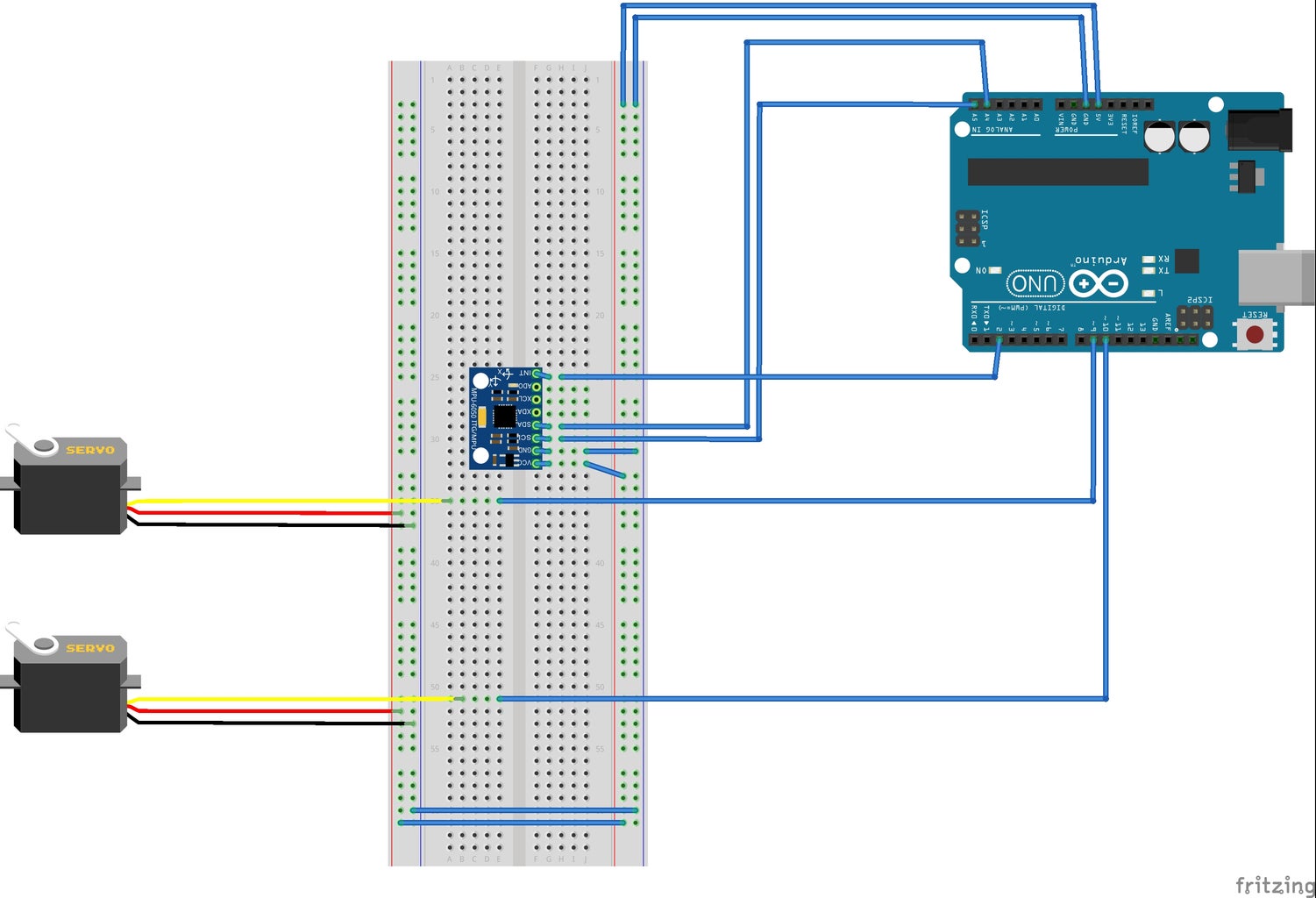
The connections should be made as shown in the Fritzing diagram.
For MPU6050:
SCL -> A5
SDA -> A4
INT -> 2
Servo1 -> 9
Servo2 ->10
After all the connections are made, upload the code onto your Arduino:
#include "Wire.h"
#include "I2Cdev.h"
#include "MPU6050.h"
#include "Servo.h"
MPU6050 mpu;
int16_t ax, ay, az;
int16_t gx, gy, gz;
Servo servo1;
Servo servo2;
int val1;
int val2;
int prevVal1;
int prevVal2;
void setup()
{
Wire.begin();
Serial.begin(38400);
Serial.println("Initialize MPU");
mpu.initialize();
Serial.println(mpu.testConnection() ? "Connected" : "Connection failed");
servo1.attach(9);
servo2.attach(10);
}
void loop()
{
mpu.getMotion6(&ax, &ay, &az, &gx, &gy, &gz);
val1 = map(ax, -17000, 17000, 0, 179);
if (val1 != prevVal1)
{
servo1.write(val1);
prevVal1 = val1;
}
val2 = map(ay, -17000, 17000, 0, 179);
if (val2 != prevVal2)
{
servo2.write(val2);
prevVal2 = val2;
}
delay(50);
}
Important note: There might be issues connecting the MPU6050, as the wires keeping running lose, so when you initially upload it, check in the serial moniter if the accelerometer was successfully connected. Else reconnect and try again.
Tips: You can add more servos by introducing new variables and mapping accordingly. Adding more powerful servos and a better structure can open new possibilities like a fpv camera mount etc
.
Always ready for feedback.
Thank you.


