Introduction: Magnetic Horizontal Water Level Switch
This Instructable walks you through the design, construction and testing of a magnetically operated horizontal water level switch.
The operation is based on a magnet fitted within a float swiveled in such a way that when it is horizontal it comes close to a normally-open reed switch switching it ON.
When the water level in the tank rises it makes the float move up and the magnet come closer to the reed switch switching it ON.
Parts designed in Autodesk Autocad are printed using an Ender 3D printer and assembled together forming the water level switch.
Supplies
Float X 1 3D Printed
Body X 1 3D Printed
Stud X 2 3D printed
Reed Switch 3 mm Diameter X 1 Generic
Magnet 20 mm X 10 mm X 5 mm X 1 Generic
Step 1: Autodesk ACAD Design
The design of f our individual parts was carried out in 3D mode using ACAD.
A Float: Houses the magnet and is made up of the intersection of a hollow cylinder and hemisphere. There is a swivel arm permitting limited rotation. The design is built in such a way that 3D printing can be carried out without any support structure.
A Body: Consists of a long cylinder closed at one end with axial hole used for accommodating the reed switch. There is also a threaded portion and fixed washer used for installation on the water tank outer surface. Provision is also made for fixing the studs at the rotation axis. As the body is a long cylindrical object and printing needs to be in the vertical direction so that the central hole is created, it is necessary to provide a large detachable cylindrical base to provide stability while printing.
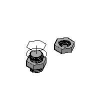
A Nut: Designed with adequate tolerance and matching thread with respect to the threaded body.
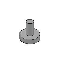
Two Studs: Which will be used for assembling the hinge and swivel.
All .DWG files are provided.
Step 2: 3D Printing
An Ender 3d printer was used with PLA filament to create the different parts.
The STL and G-Code files are provided
Step 3: Conformal Coating
The 3D Printed parts with PLA are porous and the parts specially the float would get filled with water over time. To prevent this from happening the parts are sprayed with a thin layer of conformal coating. The coating used is clear varnish which is used for protecting wired printed circuit boards.
Step 4: Assembly of the Float Switch
Reed switch assembly in body:
One contact of the reed switch is carefully bent backward. Both contacts are extended by soldering a two-core lead-in wire. The cylindrical hole in the body is then filled using waterproof glue and the reed switch with wire inserted right till the end. After partially drying the side holes for the hinge are cleared of glue. Epoxy compound is also placed the rear end of the body to support the lead-in wire.
Magnet assembly in float:
The magnet is placed in the recessed portion on the float and covered with epoxy compound.
Overall assembly.
The body and float are aligned and studs place at the hinge point. The studs are glued only on the outer side using plastic cement. The float should be free to rotate about the hinge.
Step 5: Quick Check
A multi-meter is connected to the ends of the lead in wire and the float moved around the hinge to check if the reed switch contacts close.
Step 6: Installation
The float switch is installed through a hole drilled on the side of the tank at the full level. The lead-in wires are connected to a buzzer which will give an audio alarm when the tank is full.
The buzzer power is linked to the water pump power switch. When the alarm indicates that the tank is full, switching of the pump switch also switches off the buzzer.

Participated in the
Make it Move Challenge


