Introduction: Make Your Own Arduino With Power Supply and Bootloader


Presented here is a low cost idea for making arduino at home. In this project, step by step information is provided from power supply to bootloading to program the Microcontroller.
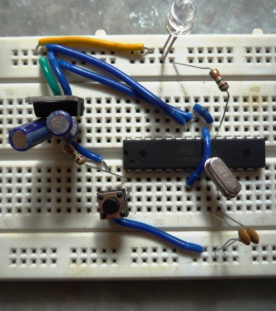
Here is the clone Arduino Board. I have used ATMEGA 8P for this project. You can use ATMEGA 328/168/8 or any Blank IC for this project of the same series.
Here various softwares are used like Arduino IDE. You should have some basic knowledge about ARDUINO UNO and its programming and applications.
Here various tiny connectors are used so one must very precisely solder all the components.
DON'T FORGET TO FAVOURITE, AND VOTE!!!!!!!!!!
So, Lets get started with the project.
Step 1: Get This!

1. ATMEGA 328/168/8 (Blank)
2. LM 7805 IC
3. 2 x 10uF Capacitors
4. 2 x 22pF Capacitors
5. 16/14/8 MHz Crystal
6. 2 x 1k Resistors
7. Breadboard Wires
8. LED
9. Tactile Switch
10. AVR Programmer(Optional)
11. USB to Serial Breakout Board(Optional)
Step 2: Knowing Your IC

This is the image of ATMEGA 8 PU pin Diagram from a website.
This will help you for further project.
Step 3: Complete Circuit Diagram

Here is the complete circuit diagram of Arduino.
Scroll down for more steps to get the complete Guide for this Project.
Step 4: Power Supply

The presented Circuit Diagram is the power supply diagram. Here LM 7805 Voltage Regulator IC is used which will convert any 5v-12v to 5v.
This will power the ATMEGA.
Two Capacitors of 10uF is used.
Mark VCC and GND on the board because ahead you will get many connections at that point.
Step 5: How To....

First of all mount 7805 on the breadbord.
Connect the first capacitor across Pin 1 and 2 and another across 2 and three.
You will give positive and negative input at pin 1 and 2 Respectively.
You will get output from pin 3. So you will get positive and negative from pin 3 and 2 Respectively.
Park pin 3 as VCC and pin 2 as GND.
Step 6: Mount the IC

Mount the IC on Breadbord near the place where you have made power supply.
Step 7: Reset System


This system will reset your system programming.
For this first connect resistor across 1 pin of IC and VCC Marked before.
Now attach switch across first pin of IC and GND Marked before.
NOw, your reset system is ready..
Step 8: Crystal System

Add 16MHz Crystal. You can also have a 14MHz crystal. I can't find any of them so I have used 8 MHz and it worked. 16MHz is recommended here.
Add 16Mhz Crystal across pin no. 9 and 10 of IC.
Then add a 22pf capacitor at pin no. 9 and other end at ground.
Add another capacitor at pin 10 and other end at Ground.
Connect pin no. 8 to Ground.
Step 9: Some More Connections!


Connect pin 22 at Ground.
Join pin no. 21, 20 and 7 of IC and Connect to VCC.
Step 10: Connecting LED

Take 1k Resistor and connect its one end at pin no. 19 of IC.
Now Connect positive terminal of LED at the end of 1k Resistor and negative terminal at Ground.
Now you connections are complete and Clone Arduino is ready on Breadboard.
Step 11: Make It on Circuit Board
Here are some tips that will help you to make this project on General Circuit Board.
First of all use the connectors as shown in the image in circuit.
Step 12: IC Base


It is hard to get narrow 28 pin IC base for ATMEGA. So the easier way is to use two 14 pin Holder and Solder them on Circuit board one after another with no space between them.
Step 13: Ready Clone
Now as your Clone Arduino is ready to lets get to the bootloading. For Bootloading you will need AVR Programmer.
Step 14: Bootloading

Now here is the image from the website that will guide you to the complete connections of the AVR programmer to the Clone Arduino.
NOw you can Bootload the IC with Arduino IDE for that you should use USB to serial Breakout Board and connect.
Step 15: FInally Did It!!
Now, you are done with your clone Arduino!!!
I hope you enjoyed a Lot!
Thanks for stopping by.....