Introduction: Make a Portable Usb Powered Led Lamp
I'm going to show you how to build a bright and cheap portable usb led lamp that you could use while doing multi purpose jobs. It's always useful to have a spotlight for example when soldering, when working on your motorbike, or when doing your favourite diy things. This device will be powered by an usb power bank so that you can take the lamp everywhere having a spotlight even when electricity is missing, and will be controlled by two buttons: power (on-off) and brightness (on-off).
Step 1: List of Materials
- 59 x bright white 5mm leds (1.50€ on ebay)
- 59 x 100 ohm resistors 1/4W (2 € on ebay)
- 1 pcb prototype board 150mm x 100mm (2€ on ebay)
- 1 pcb female usb (stripped from an old device)
- 2 pcb spdt switches (on - on)
- long thin wires
Step 2: Electronic and Schematic
The lamp will draw 500-600 ma when bright switch is off and 800-900 ma when the bright is engaged, so the power bank - or generic source - must provide at least 1A of current. Laptops provide 500ma on each usb2 port and 900ma on each usb3 port, so if you want to plug the lamp in your laptop you have to be careful and in the case modify the schematic in order to lower the current draw of the lamp.
The white led has a forward voltage of 3.5-3.6V, so it's not possible to make a series of leds in a single rail because (5V - 3.5V) = 1.5V which isn't enough to power up a second led, so we have to set all the leds in parallel and we need to compensate that 1.5V with a load resistor. The value of the resistor determines the brightness of the leds: the lower the value the brighter are the leds, but if the value is too much low the leds could die. The typical current draw for a led is 20ma, but we can push the draw down to 15ma so that the batteries last longer. Now having the voltage (1.5V) and the decided current draw (15ma = 0.015A), we can calculate the value of the resistor applying the formula [Resistance=Voltage/Ampere], so (1.5V / 0.015A) = 100 Ohm which is the value that we need for our resistors. From the formula [Power=Voltage*Ampere] we know that each resistor will dissipate (1,5V * 0,015A) = 0,0225 Watt, and we can safely place a 1/4W type resistor. With the same logic we can calculate the power of the led: [Power=Voltage*Ampere], so (3.6V * 0,015A)=0,05 Watt.
Each rail made up by a led plus a resistor would have a power consumption of (0,022W+0,052W) = 0,074W, and this value is the key to know how much rails could power up our power bank: if we know that our power bank can provide up to 500ma at 5V we have a (5V * 0.5A) = 2.5 Watt source, so the maximum number of rails would be (2.5W / 0,074W) = 33.7; since my power bank provides 1A, i can power up a maximum of (5W / 0,074W) = 67.5 rails.
Now we only have to decide the number of leds when the device is all light up and when the brightness is off (disconnecting a certain number of leds from the supply). In my configuration i decided to have a total of 59 leds, and when the brightness is off just 35 are actually working. This way when brightness is off, 35 rails will dissipate (0,074W * 35) = 2,59W which are (2,59W / 5V) = 520ma, while all the 59 rails will dissipate (0,074W * 59) = 4,36W which are (4,36W / 5V) = 870ma.
Step 3: Construction
just follow my schematic and create the matrix of leds in this way:
- first row with 7 leds
- second row with 6 leds
- repeat until you have placed all of your 59 leds disposed on 9 rows.
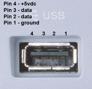
Then place all the resistors in the back of the pcb: this way the lamp will look 'prettier' leaving all the mess behind ;) the horizontal space between each led is 7 holes, while each row has a gap of 2 holes. leave disconnected pins 2 and 3 from the usb plug and just consider pin 4 as +5V and pin 1 as ground.
Step 4: Powering Up and Testing
Check for shorts: there're hundreds of soldering points, so be sure to keep everything clean. To check the draw of the lamp i used the usb charger doctor (bought from ebay for 5€), and you can see that the ratings are pretty close to our calculations. There are many factors why the ratings aren't exactly those of the calculations: first of all i used 5% precision resistors and the real value of the resistor oscillates between 95Ohm and 105Ohm, then each led has a real forward voltage between 3.2V and 3.6V. Anyway we're under the power bank limits (1A) and that's fine.
25 Comments
3 years ago
Thank you for this instructable, it is just what I have been looking for, I only have stripboard so I have to make cuts between each set, but this is great. To settle the argument on resistor values I use this site, and 100 Ohm resistors are fine. http://led.linear1.org/led.wiz
8 years ago on Introduction
Are you sure about your current draw? Because if you are, something other than your limiting resistors is keeping the current low. 900ma / 59 = 15ma an LED. With only 100 ohm resistors on your LEDs they should be drawing more than 15ma each.
I'd sooner believe you've maxxed your USB port out, and that is why you're seeing the current you're seeing. Maybe you should hook this circuit up to a more powerful supply, and see what happens then?
Reply 8 years ago
that's what i thought too, but if you calculate the resistance accross the led you will find 3.5/0.015=233 ohm, and plus the 100 ohm resistor we have a total resistor of 333ohm. Now the total draw for each rail is 5v/333 = 0.015. And 0.015 x 59 = 0.89A, so i think it's correct. Or am i missing something?
Reply 8 years ago
LED is not an ohmic device, dont bother to calculate it's resistance.
LED as a diode always eat away a fixed forward voltage (say 3.6V). So the voltage across 100ohm resistor should be 5-3.6=1.4V=1400mV. Now you can apply ohm's law, current =1400/100=14mA in each rail
Then total current drawn should be 59 x 14mA = 826mA
Reply 8 years ago
Thanks for the explanation.
So all the calculations in the project are correct, and the calculation of the resistance accross the diode, even if useless, seem to bring anyway to my conclusion that the 15ma draw comes from both led+resistor.
Reply 8 years ago on Introduction
Probably not. Far more likely is that your USB port is current limiting. Engineers are well acquainted with folks that try to draw too much current from plug in devices. So they take steps to protect circuits too.
Reply 8 years ago
I still can't understand what you're trying to say. If my usb was current limiting i wouldn't have 900ma draw but something else. We're in 3 saying that the calculations are pretty reasonable (not a big problem if there's an error of 50ma), so can you please provide to us any link or other project in which are used limiting usb ports and the related calculations to prove your theory?
Reply 7 years ago
Guys, you could argue this point for hours (and it appears you have). If you have no data sheet for the LEDs, there is no way to tell how much current they will draw except to connect one to a power source and measure the ensuing current.
Some high brightness LEDs require up to 12 Volts to operate and I think it's dependent upon the size (actual number of junctions in series). I have some which do. They are 10 W units which output 950 Lumens.
Reply 7 years ago
hello there!
the fact is that you can decide the current draw, because you know which is the starting forward voltage: in the latest project i made (always with the same kind of leds), i measured all the forward voltage of the leds, discovering an average of 3.5V-3.6V. So, taking into consideration that mine was just simple project, all the calculations were pretty good. (my leds were the classic 5mm, no fancy things)
Reply 8 years ago on Introduction
Yeah, you know.
Reply 8 years ago on Introduction
I do think you are missing something. But you are in a far better position to determine that than I am. You have your LED array in your possession, and I don't. All you really need to do is hook it up to a power source that can deliver more current to really find out too. Because my money is on your USB port is current limiting right now. I can tell you right now you are not factoring your current draw correctly for an LED. You just subtract the voltage drop from the input voltage then solve for the limiting resistor. That is typically 0.7V for many LEDs. But with modern high power LEDs that value can be different. Again, you need to determine what is going on with hardware you have in hand. I can only guess from where I am. I would rather not do that either.
Reply 8 years ago on Introduction
I think the calculations are correct.
0.7V is a typical forward drop for a normal (not light emitting) diode. Red LEDs are often about 1.8V and white LEDs are often higher than 3V, so if you datasheet says 3.2-3.6 it's probably correct.
Reply 8 years ago on Introduction
I am sorry, what data sheet? I do believe I made it clear in my comment that the forward drop varies with devices too. I really have no idea what they used, but I still doubt their calculations are made correctly. I am merely trying to point out that they are figuring for a target value, and arriving at the numbers they are looking for. But that is coincidence, not design. Well, not design on their part, at any rate.
It is my suspicion that they have just discovered the current limit of their USB port with this project. But with no way to test it on my own I cannot prove it. It has already been independently determined that they have reached their original value incorrectly. So I really do not think it is a great leap from there to assume they have made other errors as well.
I'm busy now, so good day.
Reply 8 years ago on Introduction
Well, I guess Jimmy got the figure 3.2-3.6 V from somewhere, maybe a datasheet or maybe by own measurement.
Of course forward drop varies with device, but I have never seen 0.7 V for a LED. I don't say that it don't exist (somewhere in the world it might).
I say that 3.0-3.6 V (or thereabout) is much more typical for a white LED, and if this is the case the current per LED with be 14-20mA with a 100ohm resistor in serie.
Reply 8 years ago on Introduction
I am not familiar with the new white LEDs. I have used the older colored LEDs a lot though, and they draw 14ma at 5 Volts with a 330 Ohm resistor.
Reply 8 years ago on Introduction
the USB port on any computer has its own current regulation built in. The Mother Board manufacturer can set either per port or total current on the USB controller. (multiple USB ports per controller)
The typical max current is either 500ma or 1A max / port. 500mA is typical of laptops.
If say the controller was set to 1A max in balanced mode and you have a 200mA device in one port and plug in the light in the other it would be limited to 800mA.
This would explain the currents being a bit low and give a slightly unrealistic measurement.
Reply 8 years ago
Pfred is correct, and you should use USB B instead of A!! It is a driven device, not a driving one. Cool idea though!
Reply 8 years ago on Introduction
thanks! the fact is that the lamp is cheap, so i didn't want to buy a dedicated usb B port paying extra money: i have some old devices in here and the usb came free (plus everyone in now days has a male-male usb cable, for a reason or for another, so the choice was easy).
Thanks for stepping by!
Reply 8 years ago on Introduction
The way to know for sure would be to run the light on an unregulated supply that can supply more current. I do not have that option open to me, as I do not possess the lamp in question. It is an amazing coincidence the lamp draws just under the current the USB port can supply though. Anyhow, errors in calculations and false assumptions can sometimes have negative consequences. It did not bite in this case, but it could have. Electronics is largely about keeping the magical smoke locked up in the components. Drawing too much current is often a way of releasing said smoke too.
8 years ago
very cool. excellent instructions and explanations for the layman
good work