Introduction: Make a Super Cheap 3D Printer Using Recycled Parts
Now-a-days a lot of people talk about 3D printing and the many things that it can produce. Even the president talks about it during his state of union address. While it is true that some of the technologies in 3D printing are new in high end models, most 3D printers can be built using existing technologies that have been around for decades. For example, most 3D printers use stepper motors, although the microstep technology which allows finer resolution is relatively new(perhaps). The microcontroller used in many 3D printers are based on the AVR family found in Arduino boards. While the open source firmware such as Marlin was developed based on the GRBL for CNC machines. The word "extruder" certainly is not new to those chemical engineering students. Therefore, one can learn a lot about 3D printing from old technologies found in recycled electronics. Here I would like to share with you my effort in building a cheap and simple 3D printer. The goal is not to build a super 3D printer to compete with the commercial models, but rather to learn how it works and have some fun with it.
Step 1: Build the X-axis Using a Printer Head Assembly and Stepper Motor
The other problem was that the stepper had no cog wheel on it, so I had to find one from the HP printer that fits exactly and I was lucky in finding one. See the following video to get an idea how it works.
Step 2: Test the X-axis Using Simple Arduino Thingy
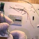
Once I made the hardware modifications, I wanted to test it by moving the printer head back and forth. I choose to use a small chip Attiny2313 which happens to be around, and the L293D H-bridge which can handle 600mA and up to 36V. It is conceptually simple to turn a 4 wire stepper. You simply turn on each wire in sequence. However, my first attempt didn't work out easily because I had the L293D placed backwards on the breadboard. I am glad it didn't damage it with the abuse. I used the Arduino software and USBtinyISP to program the Attiny2313 and now everything works fine as shown in the video.
The next steps are:
-Build the Y and Z axis
-Build an extruder
-Get a suitable microcontroller (I may initially test it with GRBL on Atmega328), then try the Mega board with Ramp1.4 and Marlin, etc.
-Calibrate the 3D printer
-Print something and have some fun.
Step 3: A Second Thought About the 2-wire Vs. Stepper Motors
When I first saw the 2 wire motor in the inkjet printer, I was confused for a moment because I was expecting to see a stepper. I replaced the 2 wire motor with a stepper because that's what everyone is using for the 3D printers. Well, it turns out that there are good reasons why a 2 wire motor is used in the inkjet printers. For one thing, it uses optical encorder strips to position precisely and with very fine resolution. By comparison, the stepper motor is basically an open loop system, meaning you tell it to make x number of turns and you trust that it will do that as a result and no feedback needed. Yesterday I read a little more about this issue and in fact there is discussion on Reprap about open vs. close loop issues for 3D printers. What I suspect is that while steppers are popular for 3D printers, it is not the only solution, or the best solution for that matter. However, since optical encorders is a little more complex than the stepper motors (whether true or not), let's just stick with the steppers for now. Later I may revert back to the original 2 wire motor with the optical encorder once I have a handle on the motor controller and feedback. So don't throw away the 2 wire motor and the optical strip yet.

Participated in the
123D Circuits Contest


