Introduction: Making an LED Illuminated Oak Bluetooth Speaker


Since getting my CNC router, I have wanted to really test its ability to produce accurate and high quality parts that would make up a finished product.
Designing and making a bluetooth speaker has been in my mind since seeing a video from DIYPerks who used a cheap amplifier/bluetooth combo circuit board. I ordered one and then a few weeks or so later saw another video where he sandwiched acrylic between wood and it was edge lit with LEDs.
So this was my inspiration and I proceeded to design the speaker!
Please check out my Instagram for more details about design choices and other stuff :)
And please vote for this project in the Box contest and the Spektrum Laser contest if you think it deserves it!
Step 1: Designing the Case/Sound Box


I started my design in Autodesk Inventor as I do with all my projects, it is a powerful design tool and gives you the ability to create amazing things quickly and easily. There are built in features for rendering which is what I used to create images you can see here.
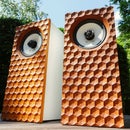
I was primarily inspired by Thodio who make beautiful wooden bluetooth speakers. I like the similarity to eyes that the speakers give and so I followed that design look. I wanted to incorporate the design that DIYperks had done witht h headphone stand so I thought I would make light rings throughout the case of the speaker. I would use LEDs to illuminate these rings.
Step 2: Making the Parts


Now I know that us CNC guys get a lot of flak from skilled wood workers for not being proper woodworkers... I don't claim to be one but I see no problem with using technology that is quite easily available (My CNC is about the price of a decent bandsaw!) to enhance your creative ability. Anyway, my project pretty much revolves around the CNC to accurately make the rings that make up the box of the speaker.
All parts were taken from the CAD software an processed in two different CAM programs. For the front panel, which had pockets to mount the speakers themselves further forward in the case (see later photos), I used MeshCam as it does all the work for me and even calculates finishing offsets and a machining margin for better chip clearance. This all helps achieve a good edge finish. For the rings that make up the body I used CamBam as it is easier to work with when doing 2D contours. This can be seen in the video I apologise for speeding it up so much but it would be a very long video if I didn't
I could really have benefited from using a laser cutter for the polycarbonate ring as a laser leaves a much cleaner edge and would have reduced the time I spent finishing the edge. I find that lasers are perhaps a tad more accurate and much cleaner! No chips to vacuum up! But alas I don't have one at the moment!
The machining took the best part of 4 hours for all the pieces so not too bad. The oak was just screwed down to the waste board of my machine whereas with the the polycarbonate I used a clean sacrificial board which was double sided taped down as it is tricky to hold the polycarb down otherwise.
Step 3: 3D Printing the Other Parts


I needed a port to allow air into the box which helps with the sound and bass levels. I designed the part in Inventor as with the rest and then 3D printed the part.
I also had always intended that this speaker was able to be charge via USB. So I found a micro USB breakout board that I designed a holder for as you can see in the photos. This allowed for a standard micro usb cable to be used to charge the device.
Step 4: Assembling the Sound Box


After all the parts were cut out, I could give them a light sanding to knock of any splinters of wood. I then used a chamfer bit in my router to cut the chamfers on the front face piece that the speakers mount to.
Then I could drill some small pilot holes on the inside for the screws that hold the speakers on as you can see in the pictures above.
Then I could test fit the body rings that make up the box to see how well they line up. Fortunately they aligned perfectly due to my use of CNC. I planned to use cycanoacrylate glue to hold everything together but I tested it with some of the offcuts of oak and it didn't hold well to the porous wood. Epoxy was the glue I settled on as it can glue pretty much anything very strongly, I had to work quickly to glue it all together as I only had 5 min set epoxy. I then used a 5 litre bottle to clamp them together.
Step 5: Finishing the Speaker Box


After everything was glued together I could set about sanding and scraping everything flush and smooth. I first glued the front panel to the rest of the box with the speakers and switch already installed. as they would be tricky to attach once it was glued to the rest of the box. I then chamfered the edges of the back panel and drilled holes then screwed it down to the box. The whole thing could then be clamped in a vice and I used a combination of sandpaper and a cabinet scraper to get the surface all around perfectly smooth and flush. Also I could use some fine sandpaper to frost over the edges of the polycarbonate to diffuse the blue light I intend to add later.
As you can see in the photos, I got the surface down to a nice smooth finish which was ready to receive a coat of sealant to prevent anything from warping not that it could because the polycarbonate glued to the oak restricts its movement.
Step 6: Electronics


I sourced the 18650 lithium batteries from a laptop battery I got off for about £5 free shipping. I like to get the batteries from this source as they are genuine and actually give the capacity that they state rather than the fake ones that claim to have a much higher capacity then they actually do. I soldered them together all in parallel so I ended up with a 3.7v 12000mah battery which is then stepped up by a DC-DC converter to 12v which is what the amplifier board needs and the LEDs too.
I wired everything up and jammed it all in the case as none of it would be seen. I dotted a few LED strips inside the case to illuminate it all.
Step 7: All Done!


It ended up really nice in my opinion, one of the nicest looking projects I have ever done! The cool glow of the blue LEDs gives it a cool image that contrasts the rustic but sleek oak endgrain.
It sounds pretty good as you can tell from the video (at the end) I posted at the beginning. its not a brilliant sound as the speakers aren't very good quality.
There were a few issues, primarily with the electronics. The DC-DC converter can't handle the current that the amp needs so it stutters a bit on the start up and gets a bit warm. I plan to change it for a more powerful one and also add more cells to the battery pack as the whole circuit draws a fair few amps for the battery back.
This is most noticeable when the speaker is at a loud volume as the LEDs dim during the low end notes. Although it is quite cool having the LEDs "dancing" to the beat :)
Anyway, thanks for reading, I hope you like this project!