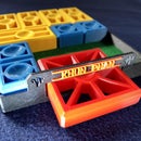
Introduction: Marble Climber - Motorized - 3D Printed
This project is about the revision and motorization of a great crank operated marble machine, to find on https://www.thingiverse.com/thing:3160563. Thanks to „3DprintedMarble“ for this little machine. I like it very much! His model is based on wooden models already published on YouTube many years ago, such as https://youtu.be/Tx2CTNYjrfE
In addition to the "motorization" this is a completely reworked project! I use the base as a container for battery, switch, AC/DC socket and wiring at the same time and therefore I had to redesign it, also the pillars.
Assembly preparations:
There are several parts in this project which are connected with screws.
So you need:
- 8x M3 x 7mm, Phillips round head screws or round head screws with slotted head.
- 1x metal sheet screw (2,2 x 9mm) for fixing the gearwheel. Alternatively you can also glue it.
For the electrics you need the following components:
- AC 125 V 6A ON-ON 3 Pins 2 Position Mini Toggle Switch
- 2.1 x 5.5mm 3-pole DC sockets connector, pin 2,1mm
- Mini DC 6V 30RPM Micro Gear Motor
- Battery clip connector with 15cm connection cable for 9V blocks
- Different colored wire
- Solder
- Soldering iron
For the running of the machine you need:
- 9V battery - to be fixed in the base (3-12V AC/DC universal power supply - for connection to the AC/DC jack)
- Many Steelballs/Marbles Ø 7mm, 12 already make a good appearance ... there should be at least 1!
After you have printed all parts start with ….
Remark:
As all parts are designed to fit very precisely, it may happen that you have to rework one or the other part a bit with sandpaper and/or cutter due to different dimensional accuracy of the printers and the different behavior of the filaments.
Attachments
Step 1:
Attach "MC_Pillar_right" to "MC_Base". You need 2 screws Ø M3x7mm plus nuts. Note that the screw on the motor housing is inserted from below!
Step 2:
Insert "MC_shaft" through the hole of "MC_Pillar_left". Then line up the 5 "MC_Cam" on "MC_Shaft". There are markings that show you where the individual "MC_Cam" must be placed. Align each "MC_Cam" with the center of the mark. Then align them as shown in the pictures (one up, one down) and glue them in place.
Then set "MC_Gear_camshaft" to "MC_Shaft". You can wait with the alignment and the fixing.
Step 3:
Now you can insert the assembled part into the hole of "MC_Pillar_right" and screw "MC_Pillar_left" to "MC_Base".
Step 4:
Now you can fix "MC_Top" on "MC_Pillar_left" and "MC_Pillar_right" with 4 screws Ø M3x7mm plus nuts.
Step 5:
Now to the motor. Before you put it in, you should solder a red and a black cable (about 10 cm long) to the pole tabs. Red to + and black to -.
When you have done this, you can insert the motor into the intended place in the "MC_Pillar_right". Feed the two cables through the hole in the "MC_Base".
The recess for the motor is very narrow. This is intended so that the motor can sit firmly. Here you will probably have to rework a little bit with a file.
If the motor fits well, you can put "MC_Gear_motor" on the motor shaft and align "MC_Gear_camshaft" so that both gears mesh. After that you can fix "MC_Gear_camshaft" with a sheet metal screw (Ø 2.2x9.5mm) or with super glue.
After that you can mount "MC_Stopper" and "MC_Motor_hood". I think you don't need to glue them.
Step 6:
Attach the switch and the AC/DC jack.
Soldering …
I'm not an electrician, so I can't give you a schematic. I enclose photos and a 3D wiring view. I hope you can see how the wiring is done.
The yellow cable is for illustration purposes only! The red or black cable can also be used in its place.
I wanted to have the option to use the Marble Climber with multiple power sources, so I wired it for operation on battery (internal), AC/DC power supply and/or solar panel.
Note: If you don't need/want an AC/DC jack, the wiring would be much easier.
Attachments
Step 7:
Final! Insert " MC_Piston_1-5" into the Marble Climber as shown in the photo.
Only for the very attentive among you:
Compared to the pictures in the video, you may notice that "Piston_1" is much narrower in the pictures in these instructions. I changed this after the video was published. It is an improvement!
Explanation: if there were a lot of balls in operation (more than 12), the first piston took up - due to the width - more than 4 balls every now and then, which could lead to 5 or more balls being brought up to the top. This occasionally resulted in these extra balls simply being thrown overboard. To prevent the first piston from picking up more than 4 balls, I've narrowed the top surface and widened the pistons 2-4 correspondingly, as well as the markings on the „MC_Shaft“.


