Introduction: Matrix-Tree
I have some PCBs flying around, if you need a small number, leave me a message!
It was December 2020, deep into the second Covid-Lockdown and I thought about how to give away some smiles for christmas to my family and friends. Besides, I wanted to have some fun with pcb-layout and microcontrollers.
The result: This cute small and relatively simple tree pcb with a Attiny44 and a 4x5 fully customizable led-matrix.
The reviews:
- 16/29: "This was the best christmas gift this year and you stole the show for everyone else."
- 10/29: "No chance you made this yourself only for us!"
- 02/29: "Can you make it go slower?" (Grandmas)
- 01/29: "I've got a torn open envelope, cool card but which tree are you talking about?" (Thanks Deutsche Post 📯)
A few weeks later I thought, maybe you would have fun with it as well as a present or a small project to learn about pcb-layout and µCs, so I made some changes to improve the design, came up with a new and not christmas-limited version and here we are. Have fun! 🎈
Supplies
- Material:
- The PCB, self made or ordered
- All electronic components from the BOM (here on findchips)
- 3D-printed stand
- CR2032 battery
- Programmer (see Step 5)
- Tools must have
- Tweezer
- Soldering Iron or Reflow Oven or alternative (see Step 4)
- Solder (-paste)
- Tape
- Tools nice to have
- Multimeter
- PCB holder / third hand
- Others
- A steady hand
Step 1: The Design
If you are not interested in some details on the schematics and design, you can skip this step.
The challenge was to control a matrix of 20 leds with fewer pins of the microcontroller. This is done by multiplexing the rows of the matrix. In the columns all anodes are connected, in the rows the cathodes. To show a pattern, the rows are switched on and off one after another very fast while the cathodes (columns) of the right leds are switched on. With this, only one led of a column is shining at the same time, so we can place the needed resistor (47R) here.
To control the rows, we need to switch the low-side of the leds. I chose a n-channel mosfet with a very low drain-source-resistance because of the current of up to four leds (~100mA). For the columns (high-side), I chose cheaper p-channel mosfets with a slightly higher resistance, it only carries the current of one led at a time. The decoration leds are switched on the low-side with the good n-channel mosfet.
I chose pull-up and -down resistors with a high value of 100k, because the energy consumption should be as low as possible.
An innovative point of this pcb is the connector for programming, which consists of copper-pads at the trunk of the tree. For more details on this see step 6.
It is very easy to change the shape of the pcb. I designed another round version, like a medal. Get creative here, change the contours and move some components. The code and circuit is the same for every pcb. If you need help with this, leave a comment!
Attachments
Step 2: Get the PCB
The most important part of the project is the pcb. There are two ways to get it.
Order it at one of the many professional manufacturers online. It is surprisingly cheap and the quality is very good. You don't have to worry about shorts or reprocessing, you can often choose the board-color and add texts and pictures to it. Most of the manufacturers have an online quoting tool where you can upload you gerber-files or even the eagle project and get a price immediately. Just google for pcb manufacturers and get some quotes.
If you want to manufacture it yourself, there are very good Instructables on how to etch, mill or print it. It is a lot of work though and you may have to change the design to have bigger traces and distances between them. I didn't try it but I recommend to order them professionally, because the board was designed for that.
I strongly recommend to invest a little bit more and order a laser cut stencil with the pcbs. See Step 4 for further information.
Step 3: Get the Components
Order all the components on this list. I will talk you through some points to consider in the selection.
- Microcontroller: It is important, that you use the ATtiny44 in the listed package. Other microcontrollers in the same package should be possible as well, but could not be programmed the easy way I describe it. Furthermore you have to change the interrupts and pins in the code for other µC.
- Button switch: Please use the one listed, others won't fit on the layout.
- Leds: You can use every color and manufacturer of the leds, as long they have the same dimensions. Please consider the current and adjust your resistors if the current differs from the provided ones.
- Resistors: The 100k resistors are pullups or -downs, so you can use other values greater than 10k if you have some flying around.
- The MOSFETs: You can use other comparable parts here, important is the difference between N- and P-Channel, the Gate-Source-Voltage and the Drain-Source resistance. Use the listed ones to be safe.
Step 4: Solder It
First: Don't underestimate how much work it is to place and solder the components. Take your time.
In principle it might be possible to solder this pcb by hand. But with a bigger number of boards and the difficult to solder leds, the advantages of working with solder-paste and an oven become clear. I strongly recommend to use a laser-cut stencil to apply the solder-paste, even though you can do it by hand for a few pieces.
See the attached layout with comments on the placement of each component.
Here is how I managed to solder 29 boards (1914 components) in 8 hours with a reflow oven:
- Clean 10 pcbs with Isopropanol.
- Apply the paste with the stencil.
- Take a deep breath to get a steady hand and place the components (see Layout_Tree.pdf).
- Put the prepared pcbs into the oven.
- Heat it up and wait for the beep.
- Take them out.
- Solder the battery holder on the bottom by hand.
- Repeat three times 🔁
If you are new to SMD- and reflow-soldering or searching for alternatives to an expensive oven, you may like this Instructable. For any other questions search the web, Instructables.com or leave a comment.
Attachments
Step 5: Check for Errors
After soldering, you have to check for shorts or not connected pins. You can do an optical check with a microscope or a good magnifying glass. Please use a multimeter to check if there are any shorts between +3V3 and GND.
Step 6: Programm It
The cool thing about AVR-Microcontrollers like the Attiny: You can flash them using a standard Arduino so you don't need an expensive programmer. You can learn how it works in the Arduino Reference here.
I wanted to have a clean and tidy pcb witout any connectors for programming on it, additionally I had to program a lot of them but each indiviually. That's why I developed a way to use the trunk of the tree as a connector. I explained in this Instructable how to build and use a expansion board for an Arduino Uno with a 6-pin pcb connector to program any AVR project. I think this a very elegant and practical way for a small series production.
If you don't want to build this expansion board and just have to program few Attinys, you also can solder the six wires to the connector pads and unsolder them afterwards.
Follow these points to set everything up for programming (without the ATtiny board plugged in):
- Arduino IDE: Go to Tools->Boards->Boards Manager...
- Search for "attiny" and install the package by David A. Mellis
- Open File->Examples->ArduinoISP
- Select the Arduino you are using as a programmer under Tools->Boards
- Upload the sketch
In the next step I will guide you throw the C-Code and how to personalize it.
Step 7: The Code
The code was written for the christmas version so it contains the snowfall seen in the video before. Some words about the thoughts behind it, if you just want to get it done skip the next bullet points.
- For a battery powered device, it is essential to use as less energy as possible when not activated. That is realized with the power-down mode, which is deactivated by an external pin interrupt and the button. Also, all unnecessary functions are deactivated (ADCs, Watchdog, etc.). Not used, the board only consumes about a few nano-amps so the battery should last a while.
- The dynamic memory of the ATtiny is to small to store the big arrays of data for the matrix. Thats why they are stored in the program memory, which makes the acces to it a little bit more complex.
Follow these steps to generate your personal text and program the µC:
❗❗❗ Remove the battery before programming the pcb ❗❗❗
- Download the two python files and put them in one folder
- Execute Skript_Text_Matrix.py and enter your text
- Copy the output-text
- Open the Arduino-Project Code_Matrix_Tree.ino in the IDE
- Insert the copied data where marked in the code (line 48)
- Select Tools->Boards->ATtiny Microcontrollers->ATtiny24/44/84
- Select Tools->Processor->ATtiny44
- Select Tools->Clock->Internal 1MHz
- Plug your pcb into the programming board
- Select the right Port under Tools and upload the sketch
- Push the button and check if everything is working
You can select to switch on or off the snowing sequence with the following line (true or false):
#define SNOWING_ON true<br>
I tried to explain some things in the code-comments as well, if a question remains, please contact me.
Step 8: Print Stand
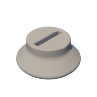
The stand was developed for the christmas-tree shape but should be useful for other shapes of the pcb as well. It is easy and fast to print, needs no support and should fit tight to the programming "nose" of your pcb (the trunk in case of the tree).
Attachments
Step 9: Ready to Go
If the programming was successful and you tested it out, put the battery into its holder (check the + on the holder for the right orientation) and enjoy the cute little matrix showing you messages!

Participated in the
Microcontroller Contest


