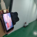
Introduction: MicroPython Program : Display the Size of the Circle
This experiment uses the MakePython ESP8266 module, which allows us to learn MicroPython programming on ESP8266. The experiment controlled the size of the circle on the screen by rotating the potentiometer. In the process, we will learn about the use of ADC, SSD1306 OLED display and the uPyCraft IDE.
Step 1: About ADC and I2C
ADC: ADC is an Analog/Digital Converter that converts Analog signals into Digital. In the front control LED on, PWM inside, we know the difference between digital signal and analog signal. The signals we use in everyday life, such as light intensity, sound waves, and battery voltages, are all analog values. If we want to measure the analog signal (voltage, light intensity, sound wave) through the single-chip microcomputer and express it by a digital signal, then we need ADC analog digital signal converter
I2C communication: I2C is widely used for controller communicating with onboard components such as sensors/ displays. Data transmission can be completed by only two signal lines, respectively clock line SCL and signal line SDA. There are only one main device Master and several Slave devices on the I2C line. In order to ensure that both buses are at a high level when idle, SDA and SCL must be connected with the pull resistor. The classical value of the pull resistor is 10K.
Step 2: Supplies
Hardware:
- MakePython ESP8266
- Potentiometer
- Bread board
- Jump line
- USB cable
MakePython ESP8266: There an onboard OLED 1.3’ OLED module on MakePython board, with 128x64 pixel... One pixel of a monochrome screen is a light-emitting diode. OLED is "self-illumination", the pixel itself is the light source, so the contrast is very high. OLED screens have I2C and SPI communication protocols, which are completely incompatible due to different protocols. In our lesson, the OLED is configured to compatible with the I2C protocol. Module purchase link: https://www.makerfabs.com/makepython-esp8266.html
Potentiometer:Potentiometer is an adjustable resistor with three leading ends and resistance values that can be adjusted according to a certain variation law. A potentiometer usually consists of a resistor body and a movable brush. When the brush moves along the resistance body, the resistance value or voltage in relation to the displacement is obtained at the output end.
Software:
- uPyCraft IDE
There many codes& programming methods with MicroPython. For this tutorial, we use uPyCraft IDE, which is the most simple& easy way for starts to skip into MicroPython.
Step 3: Wiring
This is a very simple circuit that requires very few wires, only three. Just connect the VCC pin of the potentiometer to 3.3v of MakePython ESP8266, and the OUT pin (middle) to A0, and connect the GND to each other. The OLED display uses I2C communication and the board is wired up so you don't have to worry about it.
Step 4: Installing UPyCraft IDE Windows PC
Click this link to download uPyCraft IDE for Windows:
https://randomnerdtutorials.com/uPyCraftWindows.
After a few seconds, you should see a similar file (uPyCraft_VX.exe) in your Downloads folder
Double-click that file. A new window opens with the uPyCraft IDE software.
Step 5: Establishing a Communication With the Board
After having the MicroPython firmware installed (MicroPython Firmware already installed when you get Makerfabs MakePython ESP8266), connect it to your computer through a USB cable, follow the steps:
Go to Tools > Board and select the board you’re using. Select the esp8266
Go to Tools > Serial and select the com port your ESP is connected to (download the USB driver at:
https://www.silabs.com/products/development-tools/software/usb-to-uart-bridge-vcp-drivers)
Press the Connect button to establish serial communication with your board.
You will see “>>> “ appear in the Shell window after a successful connection with your board.
Step 6: Creating the Main.py File on Your Board
- Press the “New file” button to create a new file.
- Press the “Save file” button to save the file on your computer.
- A new window opens, name your file main.py and save it on your computer.
- After that, you should see the boot.py file in your device and a new tab with the main.py file.
- Click the “Download and run” button to upload the file to your ESP board.
- The device directory should now load the main.py file. Your ESP has the file main.py stored.
Step 7: Add Driver File
Since the OLED screen uses the SSD1306 driver chip, we need to download the driver of SSD1306. You can go to the GitHub website to search and download the library of SSD1306 or click to download our ssd1306.py driver file.
After downloading, save ssd1306.py to the workSpace file directory. Then, click open the ssd1306.py file and click run, and the library file can be loaded into the device directory. At this time, the library file of ssd1306.py has been successfully loaded into MakePython ESP8266, which can be called with the import ssd1306 statement.
*note: The first time you open the uPyCraft IDE, the workSpace path does not exist. When you click, the workSpace dialog box will pop up. You can create a workSpace directory to store the user's files by selecting the directory you want to store.
Attachments
Step 8: The Main Function
Grammar explanation:
- i2c: configure the SCL and SDA pins
- oled: create OLED object
- adc.read(): Read ADC sampled data
- circle(): Custom draw circle function that USES sqrt () function to calculate the radius of the circle
- math.sqrt(r): Returns the square root of the number
- pixel(x,y,c): Draw the point at (x,y)
- hline(x,y,w,c): Draw a horizontal line, starting at (x,y), length w
- vline(x,y,w,c): Draw a vertical line, starting at (x,y), with a height of w
- oled.fill(n): Empty the screen when n=0, and fill the screen when n> is 0
- oled.show(): Turn on display function
You can either directly add this file or copy its contents to the newly created main file.
Step 9: The Experimental Results
Turn the potentiometer slowly, clockwise, and the circle on the screen will grow larger, counterclockwise smaller.


