Introduction: Mini LED Studio Light Panel
The main purpose of this project was to create something functional whilst exploring new techniques I had never used before. As I needed a small studio light for taking pictures of projects I have been working on, that is what I decided to make.
There were a few things I wanted my design to include:
- RGB + White LEDs
- Adjustable Coverage
- Mountable to a camera tripod
This instructable covers how I made it, what issues I found and the new skills I learnt.
Step 1: Materials
Required Components
- 8 x 12ohm Resistors
- 8 x 5630 SMD LED
- 8 x WS2182B LED
- 5 Pin Male Header
- 4 x M3 Threaded Inserts
- 4 x M3*6 Hex Head Screws
- Plain Single Sided Copper PCB
- Various Wire Sizes
- Black PLA
- Clear PET
Required Tools
- Soldering Iron + Solder
- Dremel With 0.8mm Drill Bit
- Ferric Chloride Solution
- 3D printer
Operating Components - Used to control the panel
- Arduino nano
- IRF3205 MOSFET + 1KOhm Resistor
Step 2: Creating the PCBs - Layout + Preparations
I designed my boards in Fusion360 so that the output file would be an STL - Ready for slicing.
Its is very important to thoroughly clean the surface of the copper using steel wool so that the ink properly adheres to the surface. If not cleaned, the ink will come off when placed in the ferric chloride, giving you an empty PCB. (Cleaning and ruined board shown in images) You can also use the steel wool to clean off failed plots.
It is important to properly secure the board whilst the printer is plotting because any small movements can ruin the traces - I did this with bulldog clips.
Step 3: Creating the PCBs - Plotting
When plotting I used a 0.2mm permanent marker with a custom mount found here (For Ender3) > https://www.thingiverse.com/thing:3388191
I'm not the best person to explain 3D Printer plotting, so here is a link to an instructable to follow > https://www.instructables.com/Draw-With-Your-3D-Pr...
Attachments
Step 4: Creating the PCBs - Etching
It is important to note before etching that Ferric Chloride is corrosive and dangerous is swallowed. In light of this I ensured that I did this work on my shed workbench whilst wearing nitrile gloves and safety glasses.
To begin I cut the plotted PCBs out with a pair of tin snips, after which I sanded the sides with various grit sandpapers. This gave the boards nice smooth sides.
Then I filled a container slightly larger than the PCB with the ferric chloride solution. I poured my ferric chloride neat, but it can be diluted to increase the area of the solution - which also increases the etching time.
The PCBs were then placed in the solution and agitated to etch off the copper. The time it takes will depend on the size of the PCB, concentration of the ferric chloride and ambient temperature.
Step 5: Creating the PCBs - Cleanup + Drilling
After the PCBs have been etched, acetone and a cotton bud was used to clean off the ink. I then checked the traces with a multi-meter in continuity mode, due to the small size of the traces some of mine were touching or had gaps in them. To fix this issue, I used a sharp craft knife to remove the touching points and soldered 0.2mm tinned copper wire where traces were meant to be.
Being happy with the previous changes, I began drilling the holes for the THT components. I did this using a 0.8mm drill bit in a Dremel. I advise doing this on top of a piece of scrap wood so the holes on the bottom are clean.
Step 6: Creating the PCBs - Assembly
LED Assembly
Required Components
- 8 x 12ohm Resistors
- 8 x 5630 SMD LED
- 8 x WS2182B LED
- 5 Pin Male Header
Once this PCB had been soldered I checked that it functioned by hooking it up to an Arduino Nano running the "Colour Pallet" Example Sketch from the FastLED Library. To test the white LEDs I ran 5v through them.
Step 7: Printing Parts
Clear PET
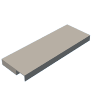
- Light Diffuser.STL
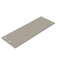
- Light Diffuser 2.STL
Black PLA
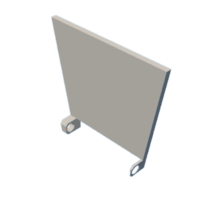
- Barn Door Left
- Barn Door Right
- Barn Door Top + Bottom
- Light Diffuser Holder
- Stand
Step 8: Light Diffuser Assembly
To assemble the light you will need:
- Light Diffuser.STL
- Light Diffuser 2.STL
- Custom LED PCB
- 4 x M3 threaded inserts
4 x M3*6 Screws
First I got Light Diffuser and using a soldering iron, melted the threaded inserts into the holes. Then Light Diffuser 2 screws into those threaded inserts with 4 x M3*6 Screws.
Step 9: Housing Assembly
The barn doors can be attached using a 3mm diameter rod. Here I used 3mm metal nails.
The M6 Nut for tripod mounting friction fits into Stand.STL which is then glued onto the back of Light Diffuser Holder.STL.
Step 10: Conclusion
Over the duration of this project I have learnt some valuable lessons and techniques. I had never plotted/etched a PCB or worked with SMD components so the results can be greatly improved as I gain experience.
The project took me 2 Days to complete. This included designing and prototyping different parts, as well as learning how to etch PCBs.
This LED panel only uses 2 Arduino pins so In the future I might look into using a Attiny to run it. I also look to integrate the microcontroller into the assembly so it is more portable.

Participated in the
Make it Glow Contest


