Introduction: Multiple Electronic Candles


Electronic candles have been posted many times on Instructables so why this one?
At home I have these small semi-transparent Christmas houses that have a LED insight and a small battery. Some houses have LEDs with a candle effect and some have LEDs that are just on. The small batteries are empty relatively fast and since I wanted to have a candle effect in all houses I decided to make it a PIC project. Of course you can turn it into an Arduino project too.
So what makes this electronic candle special? PIC and Arduino all have Pulse Width Modulation (PWM) hardware on board that can be used to create a candle effect using a LED but in my case I wanted to have 5 independent electronic candles using one controller and that is not present, at least not that I know off. The solution I used is to make these five independent PWM signals completely in software.
Step 1: Pulse Width Modulation in Software
Pulse Width Modulation has been described several times, e.g. in this Arduino Article: https://www.arduino.cc/en/Tutorial/PWM
PIC and Arduino have special PWM hardware on board that makes it simple to generate this PWM signal. If we want to make one or more PWM signals in software, we need two timers:
- One timer that is used to generate the PWM frequency
- One timer that is used to generate the PWM duty cycle
Both timers generate and interrupt when completed and so the handling of the PWM signal is done fully interrupt driven. For the PWM frequency I use timer 0 of the PIC and let it overflow. With an internal oscillator clock of 8 MHz and a prescale of 64 the formula is: Fosc/4 / 256 / 64 = 2.000.000 / 256 / 64 = 122 Hz or 8,2 ms. The frequency must be high enough so that the human eye cannot detect it. A frequency of 122 Hz is way sufficient for that. The only thing this timer interrupt routine does is copy the duty cycle for a new PWM cycle and switch on all LEDs. It does this for all 5 LEDs independently.
The value of timer to handle the PWM duty cycle depends on how we make the candle effect. In my approach I simulate this effect by incrementing the duty cycle with a value of 3 to increase the brightness of the LED and decrement it with a value of 25 to decrease the brightness of the LED. In this way you get a candle like effect. Since I use a minimum value of 3, the number of steps to control the complete duty cycle with one byte is 255 / 3 = 85. This means that the PWM duty cycle timer has to run with a frequency of 85 times the frequency of the PWM frequency timer which is 85 * 122 = 10.370 Hz.
For the PWM duty cycle I use timer 2 of the PIC. This is a timer with auto reload and it uses the following formula: Period = (Reload + 1) * 4 * Tosc * Timer2 prescale value. With a reload of 191 and a prescale of 1 we get a period of (191 + 1) * 4 * 1/8.000.000 * 1 = 96 us or 10.416 Hz. The PWM duty cycle interrupt routine checks if the duty cycle has passed and switches off the LED for which the duty cycle is completed. If the duty cycle is not passed, it decrements a duty cycle counter with 3 and ends the routine. It does this for all LEDs independently. In my case this interrupt routine takes about 25 us and since it is called every 96 us, already 26% of the CPU is used for managing the PWM duty cycle in software.
Step 2: The Hardware and Required Components

The schematic diagram shows the final result. Although I only control 5 LEDs independently, I added a 6th LED that runs together with one of the 5 other LEDs. Since the PIC cannot drive two LEDs on one port pin I added a transistor. The electronics is fed by a 6 volt / 100 mA DC adapter and uses a low drop voltage regulator to make a stable 5 Volt.
You need the following components for this project:
- 1 PIC microcontroller 12F615
- 2 Ceramic capacitors: 2 * 100nF
- Resistors: 1 * 33k, 6 * 120 Ohm, 1 * 4k7
- 6 Orange or Yellow LEDs, high brightness
- 1 BC557 transistor or equivalent
- 1 Electrolytic capacitor 100 uF / 16 V
- 1 low drop voltage regulator LP2950Z
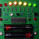
You can build the circuit on a breadboard and does not require much space, as can be seen in the picture.

Step 3: The Remaining Software and Result
The remaining part of the software is the main loop. The main loop increments or decrements the brightness of the LEDs by adjusting the duty cycle randomly. Since we only increment with a value of 3 and decrement with a value of 25, we have to make sure that the decrements do not happen as often as the increments.
Since I did not use any libraries I had to make a random generator using a linear feedback shift register, see:
https://en.wikipedia.org/wiki/Linear-feedback_shif...
The candle effect is influenced by how fast the PWM duty cycle is changed so the main loop uses a delay of about 10 ms. You can adjust this time to change the candle effect to your needs.
The attached video shows the end-result where I used a cap over the LED to improve the effect.
I used JAL as programming language for this project and attached the source file.
Have fun making this Instructable and looking forward to your reactions and results.
Attachments


Participated in the
Arduino Contest 2016


