Introduction: N64-inspired Robot Controller (Arduino + NRF24L01)


Since my first robotic project I use game controllers to execute commands and functions. This is certainly an influence of my gamer days. I already did projects with PS2, Xbox 360 controllers... but there came a time when I had some interface issues and decided to make my own controllers based on Arduino and nRF24L01 (my first controller for bigger / advanced robots: https://youtu.be/oWyffhBHuls).
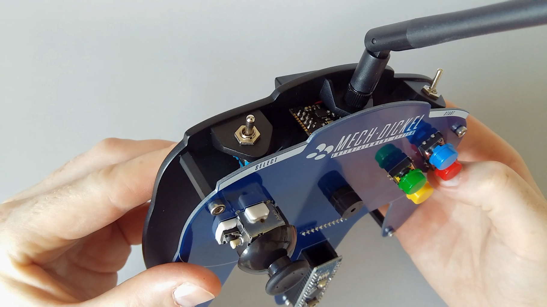
This current controller has a design inspired by the N64, but obviously with fewer buttons / functions, as it was designed to control mainly small robots and RC cars based on Arduino. The custom silkscreen and button colors are also influenced by the Super Nintendo.
Basically, the controller is a big PCB with the outline of the N64 controller. Four buttons on the right grip... analog stick on the left... a buzzer to play some tones according to the commands... a toggle switch to turn on... another toggle switch to change the function of the buttons and the stick... the middle grip is reserved for an Arduino Nano... and the commands are sent remotely by the nRF24L01 module.
Step 1: Making the PCB


The shape file was made with Inkscape, importing an image file from the original N64 controller and with the "Draw Bezier curves and straight lines" tool, I made the controller outline. (I have an Instructable focused on creating custom PCBs... please also take a look if you're interested in every step to make a complex PCB shape: How to Make Custom PCB Shapes (with Inkscape and Fritzing).)
The arrangement of the components on the board and the routing were done with Fritzing. With Fritzing I also export the files (Gerber files) necessary for manufacturing, this one made by PCBWay.


Step 2: Electronics and Soldering

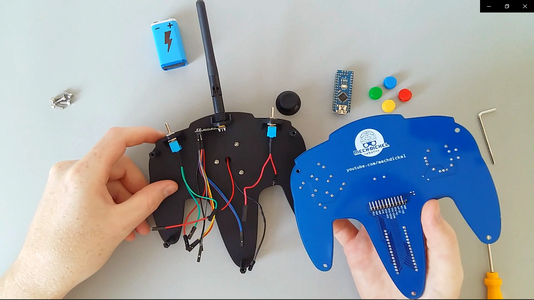
The components of this project do not require much soldering experience, as no SMD components were used. To solder the four buttons, the joystick, the buzzer and the pin headers, I used lead-free solder and a 50W iron.
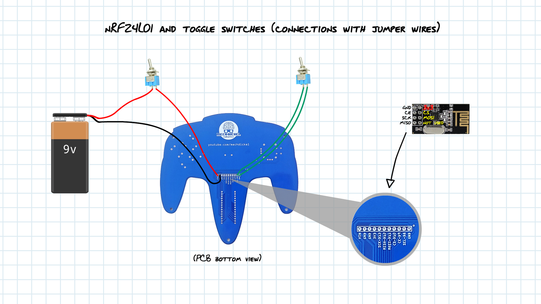
The controller also has two toggle switches, on which I soldered jumper wires, which are connected to the board as shown in the video and in the diagram.
The nRF24L01 module with antenna is also connected to the board using jumper wires.
The power supply for the controller is a 9V battery, which goes in the bottom of the base, with a battery holder.
Step 3: Making the Base


I made a base to make the controller more comfortable to handle... because it would be bad to handle by touching the pins of the components.
It's made with two layers of high impact polystyrene.
Using the PCB as a guide, I draw the outline directly on the polystyrene sheet.
With an utility knife, I cut the unwanted pieces, leaving an edge of about 1mm.
The two layers are joined with instant adhesive.
Then I remove the excess material from the edges. First with utility knife. And then with sandpaper.
The base also has brackets for the toggle switches and the nRF24L01 module with antenna.
The last step on making the base is the painting... first with spray primer... and finished with matte black.
Attachments

Step 4: Programming

The programming of the controller (actually, the Arduino Nano) is made with the Arduino IDE.
The code is very simple... for example, when I press the blue button, the controller sends 17. When I press the red button, the controller sends 18... and the receiver will take these values and the Arduino will perform the actions assigned to them.
Attached here are the code for the transmitter and two demo codes for receiver.


