

Introduction: NeoPixel Clock With SparkCore Internet Button Shield


The Spark Core Internet Button Shield only has 11 NeoPixel LEDs, but has space for and practically screams for the 12th LED to complete the circle.
And what could be more fun than making a fascinating clock with Internet connected LEDs?!
HackBergen participated in the Spark Core November 2014 Build Night, and it is nice to make something that can be reprogrammed and extended later on.
So this is a Spark Core with Internet Button Shield, installed in a cheap promo-gift clock casing and powered by a USB cable.
It is easier to read than a Binary Clock, but still a bit more challenging and interesting than a normal one.. :)
After having it in the living-room for a while it has proven that the LEDs are very usable in a darkened room and works very nice as a companion to the TV.
Step 1: What We Need


- ws2812b 5050 chip
- Thin wire from an old hard drive cable (or some other thin single core wire)
- Soldering iron and accessories
- Lupe/magnifying glass (optional)
- TackIt (optional)
- Glue
- Tweezers (optional)
- USB type A,B donor cable
- Promotional donor Clock like this one.
- 4.5mm drillbit
- Perfboard, pertinax type
- 8 pins of header male pins.
- File
- 3D printer/CNC cutter/Jigsaw - I used a Shapeoko, but a jigsaw should do the trick.
- A piece of material to make inlay of. I used an old HDPE 7mm cutting board.
Step 2: Start Soldering


Soldering SMD components can at first seem daunting, but with enough light, a good soldering iron and a little practice, is quite do-able.
Important tips:
- Use same orientation as the mounted chips.
- Use extra long wires to ease mounting.
- Use only as much solder as is really needed.
- I used TackIt to hold the chip while soldering, but a second hand or anything similar will probably do.
Step 3: Plug in Power and Test Code

It is best to test that the connections and soldering are ok and that everything works before gluing the chip to the PCB, as re-soldering will be much harder afterwards.
The silkscreen on the Spark Core indicate Vinn (5V DC) and GND (0V) which together represent an alternative power input (versus the micro USB connector) and the Spark Core instructions warn that you must NEVER use both power sources at the same time! However, you should check that your new LED chip actually works. Thus use the Vinn/GND connections to test the LED since the micro USB cable will block visibility of that same LED.
Retrieve clock code from GitHub: HackBergen SparkCore git repository
Cut/past it into the spark.io/build editor and adding the NeoPixel library should be enough to get you going.
You can change all functionality you wish in the source code, like background colors and intensity.
Check to ensure the Spark Core is connected to the cloud on the Wifi network to be used when the clock is finished, and that you can upload new code to it. The front plastic of the clock casing will make it harder to reset to firmware settings without taking it apart again, since this requires pressing the Spark Core buttons in the front.
Used this way, you will want it to always be connected to the Internet to be able to get the time.
No Internet = no usable clock.
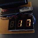
Colors as shown:
- Red = hours
- Green = Minutes
- Blue = Seconds
Step 4: Adjust Angle and Glue Chip to Board

Remember to make space for the USB cable to be connected to the Spark Core itself. Hold the chip down while the glue dries so it mounts as close to the board as possible.
I tried to use hot glue, but it was hard to get the chip to be flush to the PCB. Some type of sticky glue will probably be best, as long as it does not conduct electricity.
Step 5: Make Inlay to Hold Shield and Perfboard Together


As the Internet Button Shield has no holes for screws, I used the back part of the header connector on the shield to hold a perfboard with the inlay in-between. The inlay had to be carefully made, so the shield would be placed in the middle of the clock casing. As an added bonus, the header pins on the perfboard make it easy to solder in the USB cable for power supply later on.
This inlay could be made of a variety of materials and with different methods. It will not be seen outside of the box, so the material´s color is not important.
As our Hacker space's 3D printer is not accessible at the moment, I used my Shapeoko CNC mill to cut out a piece of old 7mm HDPE cutting board. Soft material is great for screwing wood screws into, and I was quite happy with the HDPE for this purpose.
If you do not have access to any CNC tools, you can just print out on paper the clock-2.eps file included here and use that as a template for a jigsaw.
Attachments

Step 6: Cut a Piece of Perfboard


Use a sharp knife to make a groove in the perfboard at a size that is a little bit bigger than the square hole in the middle of the inlay. Take into account that you have to solder the headers into the perfboard holes.
As the perfboard is made of very brittle material, there is no need for a very deep groove, just enough so you can squeeze and break it with just your fingers. Cutting it from both sides makes it fairly easy to break the pieces apart.
Clean up the edges with the knife and/or a file, to avoid short-circuits from copper leftovers.
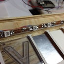
Step 7: Add Header Male Pins and Fasten Inlay Into Casing


I used 4 x 2-pin headers. If more are needed for adding more sensors later on, those are easy to add if needed.
As seen in the first picture, I had to file down some of the plastic on the header pins to make the sandwich fit as flush as possible. (0.5mm or so was filed down here.)
We only need 2 pins to power this project, but only one pin in each of the other corners seems a bit too little to create enough friction to hold the "sandwich" together.
Solder the pins in while inserted into the shield to hold the pins in the correct positions.
Step 8: Cut USB Cable and Solder Power Pins to Perfboard


I used an old USB cable that came with some old Dell monitors. These have shielding with ferrite cores were very nice.
Cut off the Host (B- square plug) part and strip it 2-3 cm.
Red and black are power wires in most USB cables. If you are unsure about your particular cable, measure with a voltmeter while powered by your computer. Better to check than having to redo it afterwards.. :)
Select the 2 power wires, cut the rest (white and green + shield) and tape them up with electrical tape.
Using a 4.5 mm bit (depending on your cable) drill a hole in the casing where it seems most practical.
Stick the power cable through the hole and tape a few times around the cable to make it bigger than the hole. This will keep it from being dragged out and stress the soldering when in use.
Solder the wires as shown in the picture. Check the Spark Core front to be sure the Vinn and GND are correctly positioned according to 5V (red) and GND (black).
Step 9: Close Up Casing


Use the original screws to close up the casing. The buttons on the Internet Button Shield are in the way of the screw holes on the lid, so it had to be rotated 60-70 degrees.
The battery lid can also be used as originally intended, and makes it possible to reach at least two of the buttons on the shield if you want it to be used for something later on.
Our program does not currently use these buttons for anything as the clock adjusts itself from the Internet.
Step 10: Watch the Time Go By..
Be fascinated by pulsing LEDs.. :)
Downloadable Video from GitHub

Participated in the
Make it Glow!


