Introduction: New Rests for Bench Grinder
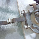
This Baldor grinder has been in my shop since 1973 and for reasons I never got around to making suitable rests for it. This photo shows what I came up with after a few moments with a measuring tape. The materials used were 3/8 X 1" and 3/8 X 4" hot rolled bar stock, which were on hand. The smaller links are 2" on center and the longer ones are 4", yours will probably vary. The rest (orange) pictured on the LHS is the finished model with 3/8" carriage bolts acting as pivots. The rests shown on the RHS are shown as a trial assembly to check the fit and to mark which pieces were to be threaded. These pivot holes were initially drilled 5/16" dia. and temporarily mounted together with 5/16" bolts. The reason for this is, 5/16" is the proper tap drill size for 3/8"- 6 coarse threads...........more on that later. All of the adjustments were located on the LHS of the rests so that the pivots are all tightened with a down stroke.
Step 1: Material Layout
Cut one piece and accurately drill out the holes (5/16" dia). You can use this as a guide to layout the balance of the four identical pieces. I am presently without a metal chopsaw, so I used a 4 1/2" angle grinder with a very thin cutting wheel. The length of each piece was marked out by clamping the sample in place and scoring the length, with the cutoff wheel, then marked the holes in the drill press. This way all the holes are drilled identically. The sets were then matched up and marked, shown in a later picture.
Step 2: Drilling
This picture shows the marking and drilling of the short pieces. Everything was initially drilled 5/16" dia. My preference was to just mark the holes with the drill bit, then come back and drill out the holes without the guide piece attached.
Step 3: Component Matching and ID-ing
These arms are matched and marked. This way if you ever need to disassemble the rest, it can easily be put back together with matching components. Regardless of how careful the layout is, there are bound to be small irregularities. These look rather rough and messy but will be cleaned up in short order, later.
Step 4: Tapping for the Pivot Bolts.
The first picture (Intro) shows a rough looking rest assembly on the right, and was assembled this way to check the fit, and to mark where the threads need to be installed. This picture shows the threading proceeding. The top member has been already drilled out to 3/8" dia. and acts as an easy guide to keep the tap on course, and straight.. The foreground hole has already been tapped.
Step 5: Fabbing the Actual Rest
This picture shows the tab welded to the rest's plates. The welding was done using a Lincoln AC 225 "buzz box" set at 105 Amp, the rod was 3/32" type 7014. If you have no welding facilities, or no friend who can do it for you, a slice off a section of heavy angle iron could be bolted in place. There appears to be much hacksaw work here, and there is if you were cutting all the parts by hand. Do youself a favour and get an inexpensive angle grinder and some cut-off wheels. Walter "Zip Cuts" are my favorites.
Step 6: Components Awaiting Final Assembly
There, we have all the pieces cleaned up and painted. No final shot is avaiable at this time as I am allowing the paint to properly set up before finally installing everything.
Step 7: Grinder Rest on LHS
Pictured here are the pieces that went into making up the rest on the LHS of the grinder. The pivots are 3/8" carriage bolts, the holes were countered bored slightly larger so that the squares under the heads could be pulled down and locked in the holes. On the second version, (the gold coloured ones) the RHS brackets were tapped 3/8 - 16 for regular bolts.
Step 8: Final Assembly
Here is everything installed and ready for work. And, the paint I found in a surplus store.


