Introduction: Overview: Autodesk Inventor Frame Generator Trailer

A large part of our welding/fabricating career is spent working with angle, channel, pipe, tube and other pre-made structural shapes. Autodesk Inventor has a specific module in the assembly environment called Frame Generator that allows you to efficiently create structures out of these standard shapes. This tutorial will guide you through how to make a basic utility trailer frame. Once we have the basics, we can create frames quickly and easily. We will be able to create drawings for individual members as well as plan materials.
Using Autodesk Inventor will also allow us to easily leverage the following CNC technologies to increase productivity and reduce complexity of advanced projects:
- CNC Tube Profilers: This equipment allows you to create pre-profiled members to ease assembly and speed up production.
- CNC Tube Benders: This equipment can bend members to specifications, creating accurate and consistent profiles for use in weldments.
This Instructable assumes familiarity with Autodesk Inventor (Inventor) Part, Assembly and sketching environments.
Step 1: Create a New Folder for Your Project
Organization is key to the success of any project, and it is especially true for Inventor assemblies. Creating a new folder for each project is important.
Step 2: Create a New Assembly in Autodesk Inventor (.IAM File)

Create a standard Assembly File. We will not deal with weldments in this tutorial, but the same module is available in weldments.
Step 3: Save Your Assembly in the Folder You Created

This step is important!! We must make sure to save our assembly for this to work. Make sure to select an appropriate name for your assembly. We want to avoid renaming inventor files, so choose an appropriate name the first time.
Step 4: Create a Part Inside the Assembly to Use As a Skeleton

Frame generator utilizes a part file with sketches to define where the members are located and how long they are. We are going to create a part inside our assembly for that purpose. Click Create to make a new part in your assembly. After you have input an appropriate name and made sure it is saving in your folder that you created in step 1, click OK and then you have to click to place the part in the assembly.
Step 5: Create a Sketch on the XZ Plane


Create the sketch shown to define the members that make up the bottom of the trailer. Use a Center Point Rectangle centered on the origin to define the perimeter. Orientation relative to the origin is important. Make sure your sketch is fully constrained.
Finish Sketch
Step 6: Create an Offset Workplane

Create a work plane offset 18in from the XZ Plane (or whatever plane sketch1 is on)
Step 7: Create a New Sketch on the Work Plane

This sketch will define the upper portion of the trailer. Place points along the sides to define the vertical member positions. Use the center point rectangle oriented on the origin to ensure that the 2 rectangles line up. Fillet the left side corners to make rounded trailer corners.
Finish Sketch
Step 8: Rename Sketches and Return to Assembly

Rename your sketches and work plane to indicate what they will be used for and return to the Assembly environment by using the return button on the top right side.
Step 9: SAVE!!!
Make sure you save at this point!
Step 10: Lets Place Some Members

Select the Design Tab and Insert Frame Members
Step 11: Lets Select a Material for the Bottom Rails


The Structural Members are organized into various standards. We are going to use the ANSI Standard.
For each standard there are Families (shapes) that can be used. We are going to select U channel
For a given family, there are various sizes. We are going to pick the C3 x 3.5 channel. This is interpreted as 3" channel that is 3.5 pounds per foot.
Step 12: Place the Bottom Rails


Click the first line
Using the flip button and rotation if required, obtain the orientation as shown.
Select the various radio buttons around the member to locate it in the correct position
Click the remaining perimeter lines to form the rectangular perimeter.
Press Apply and OK
Step 13: Place the Cross Members

Select ANSI L Equal Angles and the 2 x 2 X1/4 member
Place as cross members on all 3 mid lines, adjusting the rotation as required and orientation
Press Apply and OK once selected
Step 14: Place the Square Tubing for the Tongue and Braces


Following the same process as previous members, place the tongue tube (2 x 2 x 1/4 tubing)
Note the -3 offset to put the tube below the frame
Step 15: Change the Size of One Cross Member

Using the Change Tool we can change the size of the first angle cross member. This will allow it to touch the tongue member. Note you have to change families to Unequal Angles and select 3 x 2 x 1/4. You will have to adjust the orientation to get it correctly aligned.
Click Yes to create a new member and OK.
Cancel out of the change dialogue box
Step 16: Placing the Top Rails
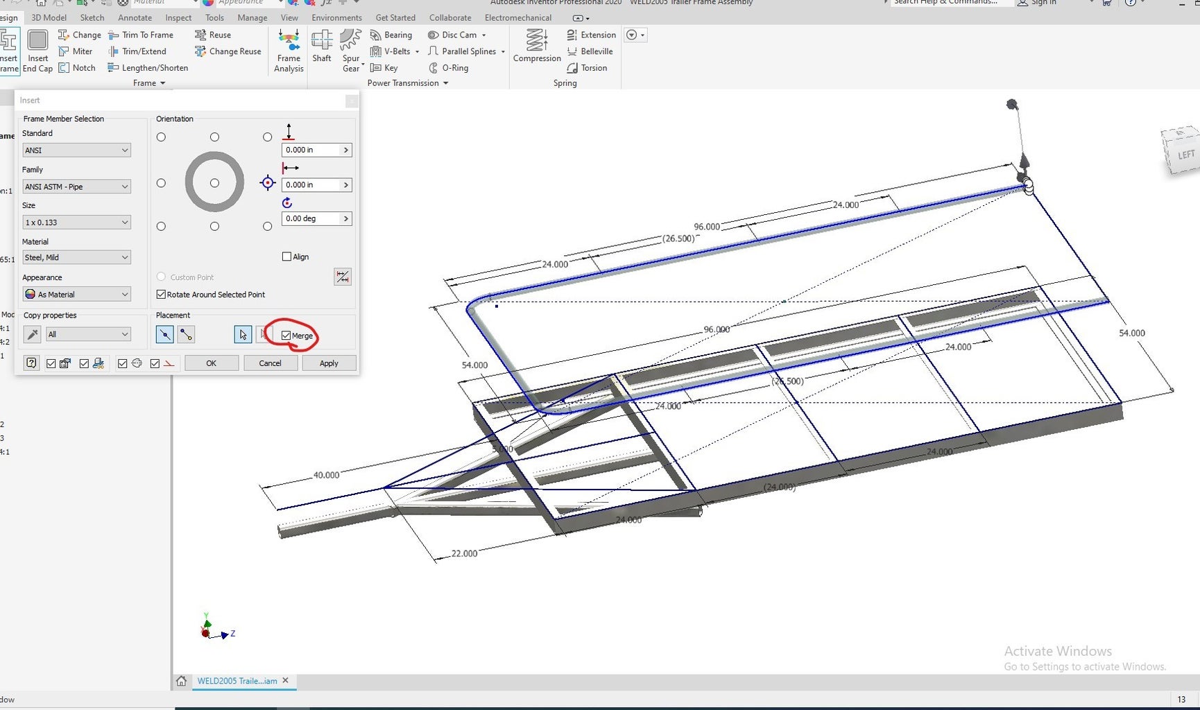
Go to Insert Frame and this time we are inserting ANSI ASTM - Pipe 1 x 0.133
Clear any offset or rotation in the dialogue box
Select the first line and get the orientation correct.
Select the remaining perimeter lines except the rear of the trailer
BEFORE SELECTING APPLY click the merge box in the lower left corner. This tells Inventor to make the top rail out of one piece of bent pipe instead of sections.
Click Apply
Step 17: Now for the Uprights

In addition to placing members on lines, we can also place members between 2 points.
Switch to point to point placement in the insert frame member dialogue box.
Select one of the end points of the lines for the cross members and select the point on the upper sketch that is above the lower point. Note we can only put one member at a time.
Click Apply
Repeat for the other verticals.
Use ANSI AISC HSS (Square) 1-1/4 x 1-1/4 x 3/16 for the rear members
Step 18: End Treatment Time

Now that all of the members are placed, its time to apply some end treatments. Before we get started, lets turn the visibility of the trailer frame skeleton off as we don't need it anymore.
Step 19: Miters First

The Miter tool create miter joints where 2 members meet. We are going to create miter joints in the corners where the channels meet.
Select the 4 channels
Apply a gap if desired
Select OK and all 4 members will be mitered
Step 20: Notches Next

We use the notch tool to notch out members to fit other members. In this case we are going to notch the cross members to the channel.
Select the frame members to be notched in selection 1 (Frame Members)
Select the 2 side channels in the second dialogue box (Notch Tool)
Click OK
Repeat the Notch for the uprights, using the top rail as the notch tool.
Step 21: Now Trim/Extend
We are going to use Trim/Extend to cut the diagonals to the face of the square tube.
Select the frame member you want to cut
Click the face selection and select the side face of the square tube.
Click Apply
Repeat for the other side
Step 22: It's Your Turn
You will notice the front does not have any vertical bars. Edit the sketches to add points and add your own front members. Turn the visibility of the Skeleton Part so see the sketches.
Step 23: Save!!
At this point you need to save.
Step 24: Now We Can Place Our Model in a Drawing

Start a new drawing just like we have done previously.
Edit the sheet size to be C size (right click, edit sheet)
Step 25: Place an Isometric View

Use Base View to place an isometric view of your trailer frame.
1/8 scale worked for me, but choose something reasonable.
Turn on Shading to make the view realistic looking
Step 26: Place a Parts List

Move to the annotate tab
Select Parts List
Select the view
Select the Structured BOM View
Hit OK twice and place the parts list in the top right corner
Step 27: Add Balloons

Using Balloon we can add Balloons to the parts
Click the Balloon Tool
Click the part you want to balloon
click where to place the balloon
Right click
Select continue
Repeat for all members
Step 28: Save Your Work!!
Make sure you save your file in the folder you created for this project!
Step 29: The Basics Are Complete

You can add views of your frame and dimension using the skills you already have. Multiple sheets would be required or view selection would need to be different. There are may options for Assembly Drawings, but this gives you the basics. Explore and experiment to fully document this trailer frame.


