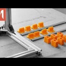
Introduction: PCB Mill - 04 - Y Axis and Motor Mount
Hi! I am JCRP and welcome to Media Milan. In this series we are building this PCB Milling machine. In the last episode I had mounted the X and Z Axis. If you want to see the entire series then you can click link here. This will be the last part of the mechanical build where I will be fixing the Y-Axis and adding the GT2 Belt and Motors. So lets get started and see how I did that.
YouTube: Visit Page
Instagram: @mrjcrp
Facebook: Kalaakaar.in
Step 1: Making the Y-Axis Plate
In Fusion360 I was able to model the exact dimension of the Y-Axis build plate. It has the linear bearing positions and where to drill holes. I printed them out in actual size on A4 and then stuck them together.
Now I can cut out just the piece that I need and use some paper glue to stick it to the MDF. This is 18mm MDF and after cutting this is the result. I am going to drill holes here to accept the linear bearings. On the top side of the MDF I am countersinking some holes to accept the head of the allen key. This would keep the surface flush.
Then mounting becomes straightforward by adding screws and nylock nuts. The smooth rods need to be parallel to each other for smooth Y-Axis motion. So I move the plate to each end and then tighten the screws.
Step 2: Making the Belt Tensioner
The next would be motor and belt mounts. This houses the motor but first we will make the belt tensioner. This is the tensioning screw and the flange bearings. I bought these from Ebay and usually used with 3D printers. All the parts are printed with 5mm thickness so they are plenty strong. Now on this flange bearing the belt can rotate on and this screw will tension the belt.
Step 3: Adding Tensioner and Motor Mount to the Frame
To attach it to the frame I can use the T-Nuts I had already included in the first episode. The belt tensioner is attached to the front of the machine. This will allow easy access whenever we need. Adding the belt tensioner to the front meant that the motor mount goes at the back.
Step 4: Mounting X-Axis Motor, Tensioner and GT2 Belt
When I designed the X-Axis I did not know where I will attach the belt. So I designed this pieces separately. But now that all is setup I can measure and add this to the fusion model. So when you download you can find the matching holes in the model.
To hold it in place I added some super glue. Once it dries its strong enough. Still I chose to add some screws for extra strength.
I am eyeballing the placement of the motor. It has to be in line with the belt holder. Then I can screw the motor holder in place. And then mount the motor to it. Here I am attaching the 20 teeth Gt2 pulley. On the other side I can now attach the belt tensioner.
The GT2 belt I used was 6mm wide and had pitch of .2mm. This is a very common one used in most of the CNC’s that you buy from Banggood. Fixing it will be as simply as rolling it through the motor and belt tensioner and connecting it back to the belt holder using zip ties. It is necessary that while making the first loop I add it as tight as possible and without much slag. Only then a little bit of tensioning can make the belt strong.
After tensioning here I am manually moving the X-Axis to see if the belt stays within the pulley.
Step 5: Adding Belt to the Y-Axis
For the Y-Axis I made this small belt holder. Again while designing I did not know the position. But now after physical construction I can measure and add it to Fusion Model. So while downloading you can see markings for this piece in the design.
I can add the belt here too. Flipping the entire machine on its side helps in mounting this. GT2 belts are manufactured with some metal linings which makes them very strong for such purposes. The GT2 belt that I used on my 3D printer works fine till date.
Step 6: Conclusion
With that mechanical build is all done. We have the X-Axis, Z-Axis and Y-Axis all done. Usually threaded rod is preferred when it comes to making a CNC. But I set out myself on a challenge to make the CNC with GT2 belt just to see how it works. And I can’t be more happier with my decision. All that remains is the adding the CNC shield, Arduino, GRBL and tweaking. Mostly electronics. So hopefully that will be last part of the series.
And to not miss the last part please subscribe to the channel. I am sure you will tons of questions which I would love to answer. Please drop them in the comments. If this video helped you learn something then please share it with your friends. Just by sharing you are helping me and this channel.
Until next time. Happy Learning.


