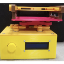
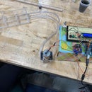
Introduction: Peristaltic Pump and Perfusion Bioreactor
We built a peristaltic pump and perfusion bioreactor system to continuously circulate a media from a pump, through tubing, into a 6-well plate, and back to the pump. This system is helpful for biomedical research purposes. Bioreactors potentially reduce the need for manual oversight, thus decreasing the possibility of human error and contamination and increasing automation, thus saving time and human labor. This system can be applied to many different types of biomedical and flow mechanic research, and its ease of use and relative low-budget compared to manufactured systems makes it accessible to many. Lastly, a major feature of this pump that makes it valuable for biomedical research is that all parts that directly contact media can be either sterilized via autoclave or otherwise purchased pre-sterilized.
Supplies
Bill of Materials
- Small Diameter Silicone Tubing
- Large Diameter Silicone Tubing
- 25G Needles
- Glass Vials + Caps with septum/membrane
- Syringe Filters
- SS Tubing
- Socket Connectors
- Plug Connectors
- Elbow Connectors
- M3 Screws
- M3 Nuts
- M3 Bearings
- M3 Washers
- 1.5A NEMA 17 Motor
- On/Off Switches
- Breadboard wire kit
- AdaFruit Perma Proto Board
- Pin Headers
- DRV8825 5x drivers
- Capacitor Kit
- 12V 6A Power Supply
Tools
- Computer
- Arduino Software
- Wire Cutters (for metal tubing)
- Scissors (for silicone tubing)
- Pliers and/or very small allen wrench for 3M screws
- Multimeter (for setting up the motor driver)
Step 1: 3D Printing and Assembling Motor Hub
3D print the motor hub, tube clips, and the 6-roller pump head from these CAD files
To assemble the pump head, take a ball bearing and slide over a 3M screw. Put the screw through the hole of one of the extending appendages of the pump head. On the other side, place a 3M washer and then secure it with a 3M nut. Repeat this process for the other 5 appendages.
Next, fit the motor hub over a 1.5A NEMA 17 Motor until it is secure. Keep the tube clips, which attach to the input and output sides of the motor hub, for later when setting up the tubing. Push down the pump head over the vertical shaft of the motor; it should fit securely within the motor hub but with room around the edges for tubing. Place a 3M nut within the square opening at the top of the pump head, and screw in a 3M screw so it is perpendicular to the shaft, thus attaching the pump head to the motor shaft that will rotate. This should all be mounted to some sort of board to maintain stability against the vibrations of the motor. The setup should look as follows (minus the tubing for now).
Step 2: Peristaltic Pump Wiring
The basic wiring diagram for the DRV8825 motor driver is above, taken from Polulu.
Due to the high current that is supplied to the motor drivers, do NOT use a standard breadboard and jumper wires (which are not built for high current applications) for connections between the motor power supply and motor driver. Instead, solder connections to a PCB where possible and use 22-23G wire for these connections. Wiring between the Arduino and the driver can use jumper wires (left side of diagram).
Arduino-Driver Wiring Notes:
- RESET and SLEEP pins should be pulled high by connecting to the positive Arduino power rail.
- STEP and DIR should be wired to specific digital pins on the Arduino to control the direction and stepping action of the motor.
- M0, M1, and M2 enable microstepping at differing intervals. The provided Arduino code is written for a 1/16 microstepping motor, which can be enabled by pulling the M2 pin high. See the above link at Polulu for more microstepping options.
- Arduino Power can be supplied either via a USB sync cable or standard Arduino barrel plug.
Motor Power Supply-Driver Wiring Notes:
- The capacitor wired in parallel with VMOT and GND should be rated for at least 47µF, 50 V to protect the driver from LC voltage spikes which can fry the electronics.
- The motor power supply should be rated according to the specifications of the Motor, as well as the number of motors being used.
- For greater control of power delivery to the motor, a power switch can be wired in series between the positive lead of the motor power supply and the VMOT pin.
Setting Motor Driver Reference Voltage:
The DRV8825 motor driver has a potentiometer (Silver circular piece in the top left near the ENABLE and M0 pins) which controls power to the motor. The readout value is known as the reference voltage, or VREF. This setting must be adjusted based on the current rating of your attached motor, and typically should not exceed 70% of the rated current of your motor to have a margin of safety.
To calculate the appropriate VREF, use the following equation:
- VREF = (Rated Motor Current / 2 ) * 0.70
- The motors provided in the bill of materials has a rated current of 1.5 A. For these motors, the appropriate VREF = 0.525 V.
- Set this voltage by twisting the potentiometer clockwise or counterclockwise very slowly with a screwdriver. The current VREF reading can be measured with a multimeter by contacting the potentiometer directly with the positive lead and the GND pin with the negative lead.
DRV8825 motor drivers should each come with an adhesive-backed heat sink which should be installed right away before use.
Step 3: Assembling Reservoir
Remove one glass vial and one septum (permeable membrane) cap from packaging. Three things will be inserted through this cap and into the vial.
- 25G needle connected directly to a syringe filter. This will act to ventilate the system.
- Approximately 1 meter of small diameter tubing attached to approximately 1.5 centimeters of the stainless steel tubing. This will be the inlet into the reservoir.
- Approximately 10 centimeters of small diameter tubing attached to approximately 4 centimeters of stainless steel tubing. This will be the outlet of the reservoir.
The needle and the stainless steel tubings should be poked through the septum cap of the vial, with the needle and syringe filter in the middle between the inlet and outlet ports.
Step 4: 3D Printing Tubing Rack and Reservoir Holder
Print the tubing rack and reservoir holder using these CAD files.
Place the tubing rack with the cut-outs facing down onto the 6-well plate. It should fit snugly and with ease. Then, place the 6-well plate into the reservoir holder, making sure it is secure. Place the reservoir into one of the attached hexagonal bases.
Step 5: Connecting Tubing
- Starting in the desired well of the 6-well plate, connect approximately 2 centimeters of large diameter tubing to an elbow connector. Place the open end in the well.
- Connect the other end of the elbow connector to approximately 1 meter of larger diameter tubing that is threaded through one of the cut outs of the tubing rack.
- Attach the end of this long line of tubing to an elbow connector. To the other end of the elbow connector connect, attach approximately 20 centimeters of large diameter tubing.
- Thread this tubing through the pump head so that it rests directly between the bearings of the pump rollers and the side of the motor hub. It should be about half-way compressed by the bearings.
- Make sure the tubing is threaded through the 3D printed tube clips at the input and output ends of the pump as they will keep the motor vibrations from dislodging the tubing. The more square-like clip (black) goes over the elbow connector; the other one (white) is for the outlet tubing.
- Attach the end of the large diameter tubing to the “rod-side” of a plug connector.
- Screw in the orange base of a 25G needle to the other end of the plug connector.
- Attach the 25G needle to the small diameter tubing that is connected to the inlet of the reservoir
- Thread outlet tubing of the reservoir through the cut out of the tubing rack and into the well of the 6-well plate that we began with. This will complete the circulation loop.
Step 6: Operation and Arduino Code
Plug the power supply into an outlet, and hook up a computer to the Arduino board output. Open the Arduino software and run the following program. This code is for one pump, but the code can be duplicated when adding additional motors.
//Peristaltic Pump Code V1 Brown University ENGN 1860
//Define stepper motor connections and steps per revolution:
#define dirPin 13 #define stepPin 12
#define stepsPerRevolution 3200 //Change based on step mode. 1/16 = 3200 s/r
int del = 4000;
void setup() {
// Decl+are pins as output:
pinMode(stepPin, OUTPUT);
pinMode(dirPin, OUTPUT);
digitalWrite(dirPin, HIGH); // HIGH == Counterclockwise
}
void loop() {
digitalWrite(stepPin, HIGH);
delayMicroseconds(del);
digitalWrite(stepPin, LOW);
delayMicroseconds(del);
}
This code controls the motor speed, which dictates the circulation speed of the pump head, thus determining the flow rate of the fluid. To control it, change the value “del = N”. "del = N" is a variable to specify delay between each step. The number of steps is set based on how the motor is manufactured (in our case, 200 full steps before enabling microstepping) and the microstepping setting based on the electronics. Regardless of the value of “del = N”, the motor will always run at 3200 microsteps (when set to 1/16 microsteps). “del = N” dictates how long it takes for the motor to complete a full revolution (a larger “del = N” means greater delay between each microstep, and thus slower RPM). Thus, to increase flow rate, decrease “del = N”. We suggest starting the system at a value of “del = 2000” to prime the tubing, and then reduce to “del = 4000” to achieve roughly a 7.6mL/hour flowrate. You must always give the pump approximately 10 minutes to equilibrate to a new speed before taking any flow measurements.
Fill the reservoir directly up with fluid (approximately 9mL). Fill the well in the 6-well plate that is in use with fluid. With the code set up, hit “Verify” and then “Upload” to upload the code to the Arduino board. Switch the On/Off switch on. Within a few seconds, you should see fluid begin to be sucked up through the outlet large diameter tubing as the peristaltic pump creates a suction force. Eventually, the fluid will circulate all the way through the tubing and into the reservoir. The high pressure system created within the reservoir by the pump will force fluid up the outlet stainless steel tubing, through the outlet small diameter tubing, and into the 6-well plate. The system will now circulate fluid on its own!


