Introduction: Picture Taking CubeSat Powered by an Arduino (UNSUCCESSFUL)


For this project, the goal was to design, build, and program a model of a Mars Orbiter. This project uses a CubeSat model and an Arduino Uno for programming.
Our CubeSat’s goal is to map the surface of “Mars” (our “Mars” is a metal sphere under a rotating rig for the Cubesat to simulate orbit) using pictures triggered by an ultrasonic sensor. Once these pictures have been taken they are imported through a dedicated Wifi shield. These are combined to create a seamless process for mapping the surface of “Mars”.
Materials:
- Arduino Uno
- Ultrasonic Sensor
- ESP8266 ESP-12E UART WIFI Wireless Shield Development Board
- ArduCam OV2640 Camera Shield
- LCD Screen
- Wires
- Breadboard
- Erector Set or Spare Metal Material
- Exterior Material of Choice (cardboard)
How It Works:
When the CubeSat is in orbit, the ultrasonic sensor detects a certain distance between the model of Mars and the CubeSat. This triggers the camera to take a picture of the model. While in orbit an LCD screen is powered to show data is being collected. From there the data and images collected from both the ultrasonic sensor and camera are stored onto the wifi shield. To transfer the data the wifi shield has connected a computer and a designated webpage will be accessed to view and further save the data.
Resources:
Arducam Tutorials:
http://www.arducam.com/knowledge-base/mini-tutorial/
Arduino References & Troubleshooting:
Step 1: Wifi Shield


Overview :
The wifi shield was ultimately the kicker in our project. After reflection, we believe that the ESP8266 wifi shield required that we send all information to it (instead of what we originally thought which was all information must be processed in the shield). If we had to do this project over again, placing the code that computes all information from the camera, ultrasonic sensor and LCD screen should be in the Arduino Uno, not the wifi shield. If the theory is correct, let us know. It would be greatly appreciated.
Step 2: Building


Material & Dimensions:
- Aluminum pieces from Erector Set
- Cardboard
- Each wall 105 mm X 105 mm
Bone Structure:
The bone structure is made from the aluminum pieces cut using a Dremel and a hand saw. These pieces were cut to size and attached by 24 screws in total with 12 smaller screws placed with square washers.
Interior Walls:
The interior walls of the CubeSat were made of cardboard, cut to size, and placed snuggly into the bone structure. The cardboard was cut slightly smaller than the size of the 105 mm bone structure. The top and bottom of the CubeSat were cut to the same 105 mm size as the bone structure and were duct-taped over the CubeSat to allow access to the Arduino and breadboard. The next step was the Dremel the holes for the ultrasonic sensor, camera, and LCD screen.
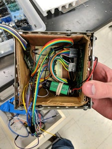
Interior Placement of the CubeSat:
Each side, for the most part, had something attached or placed inside the CubeSat. Side Wall #1 holds the LCD screen, Side Wall #2 holds the ultrasonic sensor and camera, and Side Wall #3 holds a holster for the battery. The top wall or lid holds the Arduino with the wifi shield connect to it. The bottom has a strip of velcro to attach the breadboard. All wires were a mess to put it but taping them together with corresponding ones helped to organize the space. Frankly, we ended up shoving it all in and thankfully it all works.
Stringing:
We had to thread string through the various holes in the upper bar of the CubeSat. The two ends were attached to a metal ring on the circular motion simulation above the model of Mars.
Fritzing Diagram:
Step 3: Problems & Results
Problems:
The main problem that occurred was the amount of storage on the Wifi Shield in comparison to the camera was a large difference. The Wifi shield could only store 500 KB and the size of the camera data was 5 MB. With all our sensors the wifi shield cloud not properly store all the data and be able to transfer it to the computer.
We ended up scraping the camera, LCD and ultrasonic sensor due to time constraints.
Overall, there were a lot of problems along the way such as the number of pins with the wifi shield, placement of all the sensors, breadboard, etc, and how orientation of the CubeSat in relationship to the model of Mars. within the CubeSat. In the end, the project was successful and unsuccessful in various ways. Unfortunately, our original scope of the project could not be met with our deadline.
Results:
We could not solve the memory issue or communication issue between the sensors and wifi shield. This is due mainly to a lack of time - about 5+ hours was used to attempt to solve these problems. Ultimately we were able to make the wifi shield work and the all sensors (including the LCD screen) to work exceptionally without the wifi shield. Because we did not know how to use the Arduino, before this project, we called it mainly a success due to the amount of progress we did achieve. If we had more options and time, there would be a good chance of success.
Calculations:
For our project we needed to get some calculations for a simulation through mars' atmosphere and a fly simulation. We need to calculate how many cycles are in 1 second and how many seconds are in 1 cycle. For the shake test we got 5.2 cycles (Hz) in 1 second and .19 seconds in 1 cycle. For our final flight test we needed to calculate the same thing and for that we got .67 cycles (Hz) in 1 second and 1.5 seconds per 1 cycle.
Physics:
Variables: cycles and seconds
Formulas: 1 sec/ cycles 1 cycle/ seconds


