Introduction: Portable Device to Control AC Voltage Using Arduino
In this tutorial we want to build a portable controller to control Sugar device.
Since we finished final prototype of sugar device , we asked our self this question:
How we can control Sugar device with a portable circuit , contain some Buttons , Potentiometer , LCD , build in Battery and can work for a long time before recharge the battery , And also to be a simple circuit to use and build by everyone"DIY".
the aim of this portable device is to control Sugar device in a simple way , can move it every where and test AC Lamps , AC Motors ,AC heaters , AC Pumps anywhere and with few connections
so let's see how we can build one.
Step 1: Requirements and Functionality
Before we bought any component we must decide what is the functionality of this device, How must works.
this device must have these functions:
1.LCD to show the parameters and Modes.
2.Buttons to control the parameters and move between Modes
3.Potentiometers to control dimmer Mode. 4.Power Switch ON - OFF
5.Li-ion Battery with charger
6.RJ12 Breakout to connect it with sugar device
7. Plastic case to keep all these components inside it.
last thing , we called this portable device " Sugar square " due to the rectangular shape of the device.
Step 2: What Is Sugar
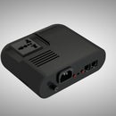
Sugar is revolutionary device designed to control AC Loads working on 110V/220V ,Designed especially For Students , teachers , Engineers and Makers How are looking for a tool to Control AC Voltage and to be easy to connect and easy to program.
With Protect cover case sugar offers a high level of safety,No electrical shock could happen and allow to anyone want to learn , design and innovate any AC power project. Sugar can be controlled through RJ12 Connector , and control The AC Output voltage using PWM , so just send PWM signal to sugar , and you will be able to control the device connected to Sugar in this way. Sugar can control AC voltage in 2 different Way:
- Control AC voltage as a Switch ON - OFF
- Control Output voltage which is suitable or many Application like AC Lamp dimmer , AC Motor speed control , AC heater temperature control.
Sugar with this features and be controlled from any Electronics platforms , Like MCU (AVR , PIC, STM ,Ti ) or Development Board (Arduino , Raspberry Pi , Beagle bone , teensy , ARM ) all you need is PWM Signal to control Sugar device. You can Read more About the features of sugar in our official website
Step 3: Components
Let's start with component we need to power on sugar:
- Sugar device (Sugar300 or Sugar1000).
- C14 Power cable
- RJ12 Cable
- Sugar RJ breakout
- LCD1602
- LCD I2C Driver
- 18650 Li-ion battery
- Button x 4
- Potentiometer x1
- Battery charger with step up circuit
- Strip board
- Solderless jumper
- Solder iron
- Nuts and screw
for some component you can replace it with what you have "Like use arduino Sensor shield instead of strip board" , you can continue the artical to see that.
for the battery,I used a battery module comes as holder for the lithium battery with charger circuit through usb and step up voltage to power the arduino ,it's like a Power bank,and you can use 9V battery if you want too.
Step 4: Measurements , Drills and Cutting
Let's start step by step understand how to build Sugar square:
1.Measure the dimensions of LCD , Buttons , Potentiometer , RJ12 Connector to cut and make Holes for them
2.cut and drill the hole for all necessary parts
3.Measure the dimensions of Battery charging port , Power switch to cut and make Holes for them.
4.As a recommendation , drill a hole for the battery in the edge of the box to fix the battery holder with the plastic case using silicon
5.install the Button and the potentiometer into the plastic case
Step 5: Assembly
6.install the LCD And I2C lcd driver , i soldered them together with strip board.
7.install Arduino board in the back side of plastic case using nuts and screws.
8. this is the name of the button , Green and red button as shown in the figure
Step 6: Assembly and Soldering
9.Now we can move to soldering job , we have 4 Buttons each one have 2 pins. we will enable pull up resistor from software , so one pin to Gnd and another pin To arduino digital pin, The potentiometer have 3 pins , +5V , Gnd , Analog Pin.
10.Now soldering the power switch with thebattery holder , from the VOUT 5V solder one wire to the power switch and another one to GND of the arduino as in schematic
11. Now let's connect the LCD ,thanks for I2C LCD driver all what we need is to connect 4 pin only as in the schematic
Step 7: Finish the Hardware Assembling
12.Fix the Battery and Power switch and solder them together
13. connect the RJ12 Breakout with arduino and fix all the component with silicon
Every thing Now is ready , As a recommendation , try to check the short circuit test between VCC And GND to prevent any damage for your components
Step 8: You Love Sugar Device ? We Need Your Help
Sugar is a startup project , designed and Manufactured the Prototypes in Taipei - Taiwan and Now sugar need your help to become a real product in the market and bring a simple tools to control AC voltage.
Sugar comes in 2 different type :
- Sugar300 : can Handle Up to 300 W
- Sugar1000 : can Handle Up to 1000 W
and both type support AC output voltage control "For Dimmer applications"
Hope you support us and become our backer Now onIndiegogo Campaign in 28th December 2016, we updated the artical ,you can visit our campaign page Here
Keep in touch with us on Facebook ,Twitter , Google+ , Instagram , Youtubeofficial accounts
Visit Our website to see all features and tutorial and see the story behind sugar
Step 9: Code
Here is the simple code at the beginning to check if everything connected in the right way.
Arduino Test code
//............................................................
#include
#include
LiquidCrystal_I2C lcd(0x20,16,2); // set the LCD address to 0x20 for a 16 chars and 2 line display
int prevRead=0;
void setup() {
lcd.init(); // initialize the lcd
pinMode(2,INPUT_PULLUP);
pinMode(4,INPUT_PULLUP);
pinMode(7,INPUT_PULLUP);
pinMode(8,INPUT_PULLUP);
pinMode(A0,INPUT);
// Print a message to the LCD.
lcd.backlight(); }
void loop() {
int Pot= analogRead(A0);
if(Pot!=prevRead)
{ prevRead=Pot;
lcd.setCursor(0,1);
lcd.print(" ");
lcd.setCursor(0,1);
lcd.print(analogRead(A0));
delay(100);
lcd.home();
} if(digitalRead(2)==LOW) { lcd.print("Hello 2"); delay(1000); lcd.home(); lcd.print(" "); lcd.home(); } if(digitalRead(4)==LOW) { lcd.print("Hello 4"); delay(1000); lcd.home(); lcd.print(" "); lcd.home(); } if(digitalRead(7)==LOW) { lcd.print("Hello 7"); delay(1000); lcd.home(); lcd.print(" "); lcd.home(); } if(digitalRead(8)==LOW) { lcd.print("Hello 8"); delay(1000); lcd.home(); lcd.print(" "); lcd.home(); } }
after we finish our campaign on indiegogo website , we will update the full code for the device and make it available to download for everyone.
Attachments
Step 10: Demo Videos
In the final we have 3 videos , an introduction video for the sugar square .
the second one a test for demo code .
the third one for the device functionality test and control AC Lamp
thank you, for more information visit our website:
and you can check the same artical in our website here

Participated in the
Arduino Contest 2016


